SPECIFICATIONS
Part No.: IS200ISBDG1AAA
Manufacturer: General Electric
Country of Manufacture: United States of America (USA)
Number of channels: 12 channels
Input span, transmitters: 1-5 V dc
Temperature: -30 to 65oC
Size: 10.16 cm wide x 33.02 cm high
Product Type: Insync Delay Board
Availability: In Stock
Series: EX2100
Functional Description
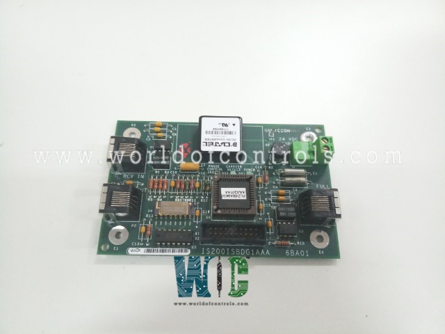
IS200ISBDG1AAA is an Insync Delay Board developed by GE. It is a part of EX2100 control system. The Insync Delay Board serves as a vital link in the control and coordination of system operations, ensuring precise timing and synchronization of critical processes. With its specialized design and robust construction, it provides reliability and performance under demanding operating conditions.
Terminal Connections and Connectors
- Terminal Connections: The PCB features four terminal connections strategically positioned to facilitate essential signal transmission and system integration. These terminals serve as crucial interface points, ensuring seamless connectivity and compatibility with external devices or subsystems.
- Additional Connectors:
- Terminal Strip (P4): Terminal strip P4 features two screw connections labeled 24 VDC Input. This connector provides a convenient interface for power supply input, facilitating the integration of power sources into the system.
- Vertical Male Ribbon Connector (P5): Connector P5 is a vertical male ribbon connector equipped with twenty pins. This connector offers versatile interface options for external devices or subsystems, enabling flexible integration and communication within the system architecture.
- Connectors P1 through P3: These connectors, labeled Full Duplex, XMIT Out, and RCV In respectively, are positioned along the board edges. They provide specific communication interface functionalities, allowing seamless integration with communication networks or peripheral devices. These connectors enhance the board's compatibility and connectivity, facilitating efficient data exchange and communication between the board and external systems or devices.
Board Components
- Test Points (TP): The board is equipped with TP test points strategically placed to provide convenient access for diagnostic and testing purposes. These test points facilitate troubleshooting and maintenance activities, allowing technicians to efficiently identify and address any issues that may arise during operation.
- LEDs: Two LEDs are integrated into the board design to serve as visual indicators. These LEDs offer real-time feedback on system status or operational modes, enhancing user monitoring capabilities. They provide a quick and intuitive way to assess the board's status, aiding in system management and performance monitoring.
- Transformers: The board features two transformers designed to fulfill vital roles in the system's operation. These transformers enable voltage transformation and signal conditioning as dictated by the system's operational specifications. They ensure that signals are appropriately processed and compatible with the board's circuitry, contributing to the overall reliability and efficiency of the system.
- Integrated Circuits (ICs): Several integrated circuits are strategically positioned on the board's surface. These ICs play diverse roles, including processing, control, or signal management functions essential for the Insync Delay Board's operation and performance. They execute complex tasks with precision, ensuring the board's functionality aligns with the system's requirements and specifications. The ICs optimize performance, reliability, and efficiency, making them integral components of the board's design.
System software features
- Controller Execution: The ACLA and DSPX microprocessor-based controllers execute the exciter control code, which is responsible for regulating the excitation system.
- Modular Structure: The software is organized into modules or blocks, each serving specific functions to create the required system functionality. These blocks are combined as needed to achieve the desired control logic.
- Storage and Memory: Block definitions and configuration parameters are stored in flash memory, ensuring their persistence across power cycles. Meanwhile, variables are stored in random-access memory (RAM), facilitating efficient data manipulation during runtime.
- Open Architecture: The exciter application software adopts an open architecture system, allowing flexibility and customization. A library of existing software blocks is available and can be configured from the toolbox to tailor the control system according to specific requirements.
- Functional Blocks: Various functional blocks are available, each dedicated to performing specific tasks. These include logic gates, proportional integral (P.I.) regulators, function generators, and signal level detectors. These blocks can be interconnected to create complex control algorithms.
- Operating Modes: The control system offers two primary operating modes: generator voltage regulation (Auto Regulation) and direct control, which can regulate either voltage or current depending on the application's requirements.
- Generator Protection Functions: Integrated within the control system are crucial generator protection functions, including over and under-excitation limiting, power system stabilization, and V/Hz limiting. These functions ensure safe and stable operation of the generator under various operating conditions and contingencies.
The WOC team is always available to help you with your EX2100 requirements. For more information, please contact WOC.
Frequently Asked Questions
What is IS200ISBDG1AAA?
It is an Insync Delay Board developed by GE under the EX2100 series.
What features does the board offer?
The board boasts advanced features such as terminal connections, additional connectors, LEDs for status indication, transformers for signal conditioning, and integrated circuits for processing functions.
How does the Insync Delay Board contribute to system reliability?
By providing precise timing and synchronization of processes, the Insync Delay Board enhances system reliability and performance. Its robust construction and adherence to quality standards ensure consistent operation even in demanding industrial settings.
