SPECIFICATIONS
Part Number: IS200ICBDH1B
Manufacturer: General Electric
Series: EX2100
Product type: Innovation Control Board
Availability: In Stock
D-Sub connector: 1
Mini-DIN connector: 1
RS-232 female 9-pin portL: 1
Ethernet jacks: 4
Conduction sensors: 2
Backplane connectors: 3
Country of Manufacture: United States (USA)
Functional Description
IS200ICBDH1B is a Innovation Control Base Board developed by GE. It is a part of EX2100 excitation system. The GE Control System is designed to provide reliable and efficient generator excitation in a range of power generation applications. The system's advanced technology enables it to handle the complex and demanding requirements of modern power plants. The multiple controllers, power bridges, and protection module work together to provide the optimal excitation solution for any given generator. The EX2100 Excitation Control generates field excitation current to control the ac terminal voltage of the generator and/or the reactive volt-amperes. It is a complete static excitation system for generators on new and retrofit steam, gas, and hydro turbines.
Features
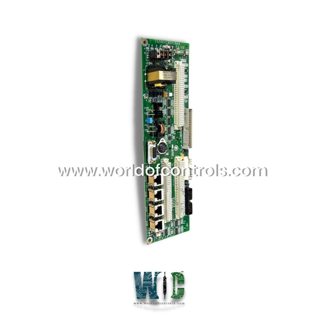
- ICBDH1B is intended to serve as an auxiliary board. It's a small, rectangular-shaped board with numerous inputs and outputs. There are five pre-drilled openings on the board, one in the center and one at each corner. Conduction sensors account for two of these.
- Three female backplane connectors are located near the center of the board surface.
- A single reset switch, several integrated circuits, three transformers, a fuse, and four transistors are also present on the board.
- There are three backplane connectors (female.) Each backplane connector has a "Pin 1" designation.
- Four jack connectors (female.) These are labeled J11A/J11B and J12A/J12B and are placed side by side.
- There is one 9-pin D-Sub connector (female.) This is known as J9.
- There is one 8-pin mini-DIN connector (female.) This is known as J10.
- Four stab-on connectors. These are referred to as Chas1/Chas2 and CCom1/CCom2.
- There are two conduction sensors.
- Four male vertical pin connectors ranging in size from 9 to 40 pins.
Characteristics
- One of the key benefits of the EX2100 Excitation Control System is its ease of integration with other power generation systems. This integration ensures seamless operation and helps minimize the risk of system failure. The system can be integrated with turbine controls, static starters, distributed control systems, and human-machine interfaces (HMI) without the need for third-party interfaces or gateways. This makes the EX2100 Excitation Control System an ideal choice for power plants that require an advanced and flexible excitation solution.
- Another advantage of the Excitation Control System is its advanced protection features. The protection module provides a range of protection functions to ensure that the generator is protected from faults and malfunctions. This includes over-voltage protection, under-voltage protection, over-current protection, and over-speed protection, among others. These protection functions help ensure the safe and reliable operation of the generator and the overall power generation system.
- Backplane connectors are built along the rear board edge of the cards that plug directly into rack systems. This enables simple plug-in/plug-out capability, which simplifies component maintenance and replacement.
Software Features
- The exciter control code is executed by microprocessor-based controllers (ACLA and DSPX). The software is made up of modules (blocks) that work together to provide the necessary system functionality. Variables are stored in random-access memory, while block definitions and configuration parameters are stored in flash memory (RAM).
- Traditional analog controls are emulated by the exciter application software. It employs an open architecture system with a library of pre-configured software blocks from the toolbox.
- Individual blocks, such as logic gates, proportional integral (P.I.) regulators, function generators, and signal level detectors, perform specific functions. The control switches between two modes: generator voltage regulation and direct control.
- The control incorporates generator protection functions such as over and under-excitation limiting, power system stabilization, and V/Hz limiting.
Hardware Features
- Auxiliary cabinet for field flashing and protection circuits such as de-excitation and shaft voltage suppression
- Power conversion cabinet containing SCR cells, cooling fans, dc contactors, and an ac disconnect
Control System Toolbox Connection
- The exciter backplane's toolbox connector accepts an RS-232C cable, which connects an external computer to the DSPX board.
- This connection is only for maintenance. To communicate with controllers M1, M2, and C, three 9-pin connectors are located at J303B, J310B, and J313B.
WOC is happy to assist you with any of your automation requirements. Please contact us by phone or email for pricing and availability on any parts and repairs.
FREQUENTLY ASKED QUESTIONS
What is IS200ICBDH1B?
It is a Innovation Control Board developed by GE
What is the board used for?
It is an auxiliary board designed to serve as a supplement to the GE Energy EX2100 Excitation Control System. Its primary function is to provide additional inputs and outputs to the exciter within the control system.
What are the inputs and outputs of the board?
The board has a variety of inputs and outputs, including one 9-pin D-Sub connector, one 8-pin mini-DIN connector, four jack connectors, four stab-on connectors, and four vertical pin connectors (male). It also includes five pre-drilled openings for conduction sensors and three female backplane connectors.
What are the backplane connectors on the board labeled?
The connectors on the board are labeled with a Pin 1 designation.
What are the jack connectors on the board labeled?
The board are labeled J11A/J11B and J12A/J12B and are placed side by side.
What are the stab-on connectors referred to as?
The stab-on connectors are referred to as Chas1/Chas2 and CCom1/CCom2.
