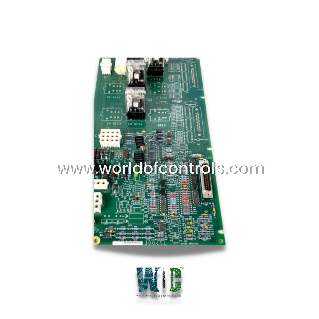
IS200EXHSG4A - High-Speed Relay Driver Board

IS200EXHSG4A - High-Speed Relay Driver Board IS200EXHSG4A - High-Speed Relay Driver Board

World Of Controls understands the criticality of your requirement and works towards reducing the lead time as much as possible.

IS200EXHSG4A - High-Speed Relay Driver Board is available in stock which ships the same day.

IS200EXHSG4A - High-Speed Relay Driver Board comes in UNUSED as well as REBUILT condition.

To avail our best deals for IS200EXHSG4A - High-Speed Relay Driver Board, contact us and we will get back to you within 24 hours.

SPECIFICATIONS

Part Number: IS200EXHSG4A
Manufacturer: General Electric
Series: EX2100
Product Type: Exciter High-Speed Relay Driver Board
Availability: In Stock
Control Type: Simplex
Contactor Type: Standard contactor (125 V dc coil)
Type: 500 A, 42 mm bridges
Country of Manufacture: United States (USA)
Manual: GEI-100475A

Functional Description

IS200EXHSG4A is an exciter high-speed relay driver board developed by GE. It is a part of EX2100 Excitation system. The Exciter High-Speed Relay Driver board is used in the EX2100 Excitation Control and provides drivers for the dc contactors (41) as well as pilot relays for field flashing and de-excitation. Through the Exciter Backplane Board, these boards connect to three Exciter Main Input/Output Boards (EMIO, redundant control) or one EMIO board (simplex control) (EBKP).

Features

  • On the board are pilot relays for the flashing relays 53A and 53B, as well as pilot relays for the de-excitation relay KDEP.
  • The Exciter De-Excitation Board (EDEX) de-excitation status signals are conditioned on EXHS and sent to EMIO. Crowbar status signals are conditioned on EXHS and sent to EMIO from the EXDE De-Excitation Control Board.
  • On EXHS, three contact inputs from 41, 53A, and 53B are powered by 70 V dc and their feedback is monitored. The contacts are powered by the exciter power supply. The status signals generated are sent to the EMIO.

Contact Inputs

  • Contacts 53A, 53B, and 41 are brought into EXHS for EMIO monitoring. The contact input uses are similar in the simplex and redundant cases; however, for redundant control, the inputs are fanned to the M1, M2, and C controllers.
  • Signals in simplex control are only routed to the EMIO in the M1 controller. The three contacts are wetted by EXHS's 70 V dc supply. Power is isolated and supplied to the contacts via resistors from plugs J12M1 and J12M2. The wetting voltage can range between 63 and 84 V dc.
  • The resulting signal is distributed to M1, M2, and C, while the contact input monitoring circuit is located on EMIO.

Application Data

  • The close function contactor drivers are K41 (M1, M2, C), and the flashing pilot relays are K53A and K53B.
  • The single de-excitation pilot relay is KDEP. J505, J508, and J515 are 25-pin connectors for cables to the EMIO boards M1, M2, and C. They carry similar signals and have similar wiring, with the exception that J505 is connected to M1, J508 is connected to M2, and J515 is connected to C.
  • However, J515 lacks de-excitation and crowbar signals. For auxiliary contact wetting, plugs J12M1 and J12M2 bring in 70 V dc from the M1 and M2 power supplies.

Board Replacement Procedure

  1. Ensure that the exciter has been deactivated.
  2. Inside the control cabinet, ensure that all electrical I/O circuits are turned off before touching them.
  3. To simplify reconnection, ensure that all cables are labeled with the correct connector name (as marked on the board), then carefully disconnect all cables from the EXHS board. Before removing any mounting hardware, place a rag or other nonconductive barrier beneath the EXHS board (above the board rack). Dropping a clip or any hardware into the equipment could result in equipment damage, personal injury, or an exciter trip while the EX2100 is turned on.
  4. Remove the screws holding the EXHS board to its mounting and the board itself.
  5. Verify that the replacement board is the same type (G1 or G2) as the original one.
  6. Install the new EXHS board on its mounting with the screws removed in step 4 and orient it in the same position as the one removed.
  7. Reconnect all cables to the EXHS board as labeled, making sure they are properly seated on both ends. Shut the control cabinet door.

Functional Comparison-EXHSG4A vs. EXTB

  • EXHSG4A shares many similarities with the exciter terminal board. However, it differs significantly by replacing the forty-one DC contactors found on the EXTB with a solid-state relay driver.
  • Additionally, this board features two conduction sensors, identified as E1 and E2.


WOC is happy to assist you with any of your automation requirements. Please contact us by phone or email for pricing and availability on any parts and repairs.

FREQUENTLY ASKED QUESTIONS

What is IS200EXHSG4A?
It is an exciter high-speed relay driver board developed by GE

What is the Exciter High-Speed Relay Driver board used for?
The Exciter High-Speed Relay Driver board is used in the EX2100 Excitation Control system to provide drivers for the dc contactors (41) as well as pilot relays for field flashing and de-excitation.

What are pilot relays?
Pilot relays are relays that are used to control other relays or devices. They typically have lower current and voltage ratings than the devices they control.

What are the flashing relays 53A and 53B?
The flashing relays 53A and 53B are relays that are used to initiate field flashing of the generator. Field flashing is a process of energizing the generator field to produce a magnetic field before the generator is started.

What is the Exciter Backplane Board?
The Exciter Backplane Board is a board that connects the Exciter High-Speed Relay Driver board to the Exciter Main Input/Output Boards (EMIO) in the EX2100 Excitation Control system. It is used in redundant control systems where there are three EMIO boards, or in simplex control systems where there is one EMIO board.

What is the Exciter De-Excitation Board?
The Exciter De-Excitation Board (EDEX) is a board that is used to control de-excitation of the generator. De-excitation is the process of removing the magnetic field from the generator to stop the generation of electricity