SPECIFICATIONS
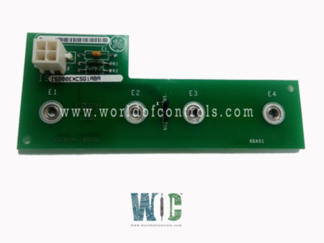
Part No.: IS200EXCSG1ABA
Manufacturer: General Electric
Country of Manufacture: United States of America (USA)
Size: 33.0 cm high x 17.8 cm wide
Technology: Surface mount
Temperature: -30 to 65oC
Number of Conduction Sensors: Four
Manual: GEH-6632
Product Type: Exciter Conduction Sensor Board
Availability: In Stock
Series: EX2100
Functional Description
IS200EXCSG1ABA is an Exciter Conduction Sensor Board developed by GE. It is a part of EX2100 control system. The Conduction Sensor Board (EXCS) plays a critical role in the EX2100 Excitation Control system by detecting bi-directional current flow through a bus line. The EXCS board is installed within the Power Conversion Module (PCM) cabinet. It features a single 4-pin connector (P1) and does not include any fuses, test points, LED indicators, or components.
Role in Excitation Control System
- Current Detection: The primary function of the EXCS board is to detect bi-directional current flow through a bus line within the EX2100 Excitation Control system. This enables precise monitoring of electrical currents, ensuring the system operates within safe parameters.
- Integration with Excitation Control Components: The EXCS board is an integral part of the excitation control system, working in conjunction with other boards such as the Exciter Gate Pulse Amplifier Board (EGPA) and the Exciter Main Input/Output Board (EMIO).
Power Source and Filtering
- The Exciter Gate Pulse Amplifier Board (EGPA) serves as the power source for the EXCS board. This arrangement guarantees a consistent and dependable power supply crucial for the smooth operation of the control system.
- In addition to providing power, the EGPA also performs output filtering on the signals generated by the EXCS board. Before transmitting these signals to the Exciter Main Input/Output Board (EMIO), the EGPA filters them to remove any noise or interference. This ensures that the output signals are clean and stable, contributing to the overall reliability and performance of the control system.
Current Detection Mechanism
- Sensor Configuration: It utilizes two unidirectional Hall Effect sensors positioned to face in opposite directions. These sensors are strategically placed to detect current flow accurately and reliably.
- Detection Principle: When either sensor detects a magnetic field above its operating threshold, indicating the presence of current, it produces a logical low output. This output remains low until the magnetic field drops below the sensor's release point.
- Logical Output: The logical output generated by the sensors provides valuable information about the current flow status, enabling the excitation control system to make informed decisions and take appropriate actions as necessary.
Current Detection Mechanism
- Gapped Steel Rings: The board is equipped with gapped steel rings attached to it. These rings are positioned such that the bus line passes through them. The Hall Effect sensors on the board measure the concentrated magnetic flux produced within the rings.
- Hall Effect Sensors: Utilizing Hall Effect sensors, the board accurately detects the magnetic flux generated by current flow through the bus line. This detection mechanism ensures precise monitoring of current levels.
- Mounting Bracket: A plastic mounting bracket is employed to securely mount the EXCS board directly onto the bus line and hold the steel rings in place. This ensures stable and reliable operation of the current detection system.
Power Requirements
- Necessitates a power supply input of +12.0 V DC with a tolerance of 5 percent. With a maximum power consumption of 0.3 watts, this input voltage is crucial for the proper functioning of the board. The EGPA (Exciter Gate Pulse Amplifier) board serves as the source of this power, guaranteeing consistent and reliable operation.
- To facilitate the power supply connection, the power supply input and the 12 V DC return are linked to the EXCS board through the EGPA board. This arrangement ensures a seamless transmission of power between the two components, contributing to the overall stability and performance of the control system.
Logical Output Signals
- Redundant Outputs: Produces two identical logical output signals to ensure redundancy and enhance system reliability. These outputs provide valuable information about current flow status.
- Output Characteristics: A logical low output is defined as less than 1.2 V DC, while a logical high output is above 11 V DC. These distinct output characteristics facilitate easy interpretation and integration with other components of the excitation control system.
- Connection: All inputs and outputs from the EXCS board are routed through the 4-pin P1 connector to the EGPA board. This streamlined connection ensures efficient communication between the EXCS board and the EGPA board.
EGPA Board Integration
- Power Distribution: The board powers three EXCS boards, with one board dedicated to each bus line. It also filters the output signals from each EXCS board, ensuring clean and reliable signal transmission.
- Information Transfer: The board transfers the filtered output signals from the EXCS boards to the EMIO (Exciter Main Input/Output) board. This information transfer enables centralized monitoring and control of the excitation control system.
The WOC team is always available to help you with your EX2100 requirements. For more information, please contact WOC.
Frequently Asked Questions
What is IS200EXCSG1ABA?
It is an exciter conduction sensor board developed by GE under the EX2100 series.
How does the EXCS board detect current flow?
It utilizes gapped steel rings and Hall Effect sensors to detect the magnetic flux generated by current flow through the bus line. The sensors measure this flux, providing precise current monitoring capabilities.
What are the characteristics of the logical output signals from the board?
The board produces two identical logical output signals, with a logical low output defined as less than 1.2 V DC and a logical high output above 11 V DC. These outputs are transmitted to the board for further processing.
How is redundancy ensured in the output signals from the board?
Redundancy is achieved by generating two identical logical output signals from the EXCS board. This redundancy enhances system reliability by providing backup signals in case of signal loss or failure.
