SPECIFICATIONS
Part Number: IS200EXAMG1A
Manufacturer: General Electric
Country of Manufacture: United States (USA)
Series: EX2100
Function: Inspection Card
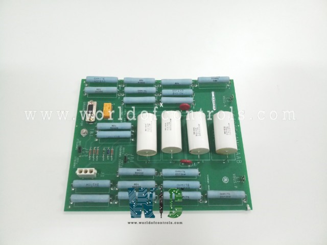
IS200EXAMG1A is an Exciter Attenuation Module developed by GE under the Mark VI series. The ground detection system for the EX2100 Excitation Control is provided by the Exciter Attenuation Module IS200EXAM (EXAM) in conjunction with the Exciter Ground Detector Module IS200EGDM (EGDM). The EXAM is housed in the auxiliary cabinet's High Voltage Interface (HVI) module. It attenuates the field bus and the EGDM by sensing high voltage from the bridge and scaling it to a usable level. The Exciter Power Backplane IS200EPBP connects the EXAM and EGDM(s) (EPBP). The EXAM and the EPBP are linked by a single 9-pin cable. The EGDMs connect to the EPBP via a 96-pin connector, P2. For simplex and triple modular redundant (TMR) applications, only one EXAM is required, and the interconnection is the same.
IS200EXAMG1A Functional Description
- In some EX2100 models, the EXAM board interfaces with the exciter/regulator options board (EROC) rather than the EGDM board. EROC and EGDM have the same ground detector functionality. The Digital Signal Processor Control Board provides computational power for the EX2100 ground detector (DSPX). The EXAM board is also used in the PGDM standalone simplex ground detector product. The PGDM employs interface boards BGTB and BFGD, as well as a processor board BPPB. These boards perform similarly to the EX2100-based boards.
- The bus voltage is distributed across the attenuation resistors (RA1 - RA4) and sense resistors when the field ground test is enabled (Rx, Ry, Rz). The test has a time limit of 10 seconds. When an alternating current bus is dead short to the ground, the entire bus voltage is present across a single section of the attenuation resistors. A fault is generated in the event of a dead short, and the exciter is shut down within 10 seconds. The EGDM controls the activation of the field ground test and master selection. The EGDM is in charge of a relay on the EXAM. The relay has a 24 V dc coil with diode suppression and operates on less than 20 mA.
- The relay is de-energized in its default state and feeds back to the M1 section in the TMR control, or to the only control in a simple application. An activated relay will feed back to the TMR control's M2 section.
Application Data
There are no test points, fuses, or LED indicators on the EXAM module. Two plug connectors, two stab-on connectors, a ground connection terminal, and three adjustable jumpers are included in the module:
- Connector J2 is a 9-pin D connector for the test signal, relay control, and leakage current.
- Connector J1 is a three-pin locking connector for the cable to the field flashing relay auxiliary contact.
- Stab-on connectors E1 and E2 connect the field bus voltages to the attenuator module.
- Terminal TB1 connects the EXAM board shield ground to the chassis ground in the cabinet.
IS200EXAMG1A Board Replacement
To replace the EXAM module in an EX2100, follow the procedure:
- Ensure that the exciter has been deactivated. (For complete de-energizing procedures, refer to the EX2100 Installation and Startup Guide, GEH-6631, and follow all local lock-out/tag-out practices.)
- Open the auxiliary cabinet door and, using high-voltage equipment, test any electrical circuits before touching them to ensure that power is turned off.
- Disconnect all cables from the EXAM board with care as follows:
- To facilitate reconnection, ensure that all cables are labeled with the correct connector name (as marked on the board).
- Unplug the two stab-on connectors, J1 and J2, as well as the wire to TB1.
- Carefully remove the board from the Glastic bracket by unseating it from the mounting pins.
- Verify that the jumpers JP1 JP3 on the new EXAM module are correctly set, as they were on the original board.
- Firmly secure the replacement board to the plastic bracket.
- Reconnect and tighten the cables that were disconnected in step 3.
Close the door to the auxiliary cabinet.
WOC has the largest stock of Speedtronic Mark VI control spares. Our team of experts is available round the clock to support your EX2100 needs.
FREQUENTLY ASKED QUESTIONS
What is IS200EXAMG1A?
IS200EXAMG1A is an Exciter Attenuation Module developed by GE under the Mark VI series.
Is the component compatible with TMR and Simplex systems?
Yes, the component is compatible with TMR and Simplex systems.
What is the application of this module?
The ground detection system for the EX2100 Excitation Control is provided by the Exciter Attenuation Module IS200EXAM in conjunction with the Exciter Ground Detector Module IS200EGDM.
