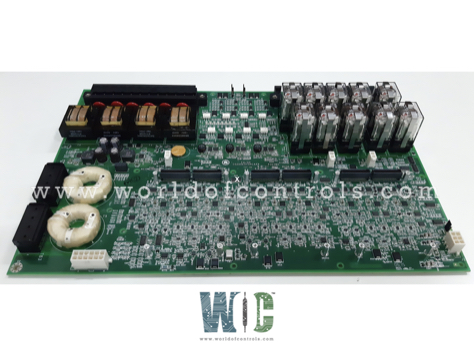
World Of Controls understands the criticality of your requirement and works towards reducing the lead time as much as possible.
IS200ESYSH1A - Excitation Control System I/O Interface Module is available in stock which ships the same day.
IS200ESYSH1A - Excitation Control System I/O Interface Module comes in UNUSED as well as REBUILT condition.
To avail our best deals for IS200ESYSH1A - Excitation Control System I/O Interface Module, contact us and we will get back to you within 24 hours.
SPECIFICATIONS:
Part Number: IS200ESYSH1A
Manufacturer: General Electric
Series: EX2100e
Product Type: Excitation Control System I/O Interface Module
Number of input channels: 24
Input isolation in pack: 1500 V
Input Voltage Range: 5V DC / 24V DC
Output Voltage Range: 5V DC – 250V AC
Potential Transformer Inputs: 4 x 120V AC
Number of relay command channels: 12
Operating Temperature: 0°C to +55°C
Mounting Type: DIN Rail
Size: 15.875 cm high x 10.795 cm wide
Country of Origin: United States
Availability: In Stock
Manual: GEI-100772
FUNCTIONAL DESCRIPTION:
IS200ESYSH1A is an Excitation Control System I/O Interface Module Manufactured and Designed by General Electric as Part of the EX2100e Series used in Excitation Control Systems. The EX2100e Excitation Control System I/O Interface (ESYS) module interfaces basic I/O external to the exciter with the control system. It handles most of the system I/O interfaces, including PT and CT inputs, digital control inputs, customer analog I/O, general-purpose relays, and trip relay outputs. The interface to the customer I/O is through pluggable screw terminal boards and the interface to the EX2100e control system is through HSLA high-speed serial link (HSSL) daughter boards that are mounted on the ESYS. The ESYS module is used in both the static and regulator systems.
CUSTOMER I/O:
INSTALLATION:
The ESYS module is normally pre-installed in the EX2100e control cabinet, but it can also be part of a field-installed kit. To protect it from flexing, the ESYS is installed in a plastic carrier that consists of two identical halves. The two halves fit together to support the entire perimeter of the ESYS. Two screws hold the carrier to the ESYS and six mounting holes hold the assembly (ESYS, PT, and CT disconnect switches) to a metal bracket. Two additional screws provide the grounding of ESYS eyelets through the carrier and into the grounded bracket.
OPERATION:
The ESYS board receives a 28 V dc input for each of the three sections. This input is used directly by the ESYS and is also fed to each respective HSLA. Each HSLA produces 3.3 V dc, which is also used by both the ESYS and the HSLA. All other voltages required on the ESYS board are locally generated from the 28 V dc for that section. The M1 and M2 sections produce 55 V supplies for contact wetting of the eight discrete input circuits. Redundant power supplies allow any one section of the ESYS to be powered down and backed up without affecting the continuous system operation of the redundant versions of the EX2100e.
The HSLA and ESYS boards provide under-voltage detection on each supply created on the boards. The ESYS provides an out-of-tolerance signal to the HSLA for the annunciation of the EX2100e control. The ESYS also receives Power Good status from up to four external inputs. The control uses these signals to monitor the health of redundant power sources or power supplies. The power supply monitor connector is a 6-pin pluggable mini connector. A logic low level (less than 1 V dc) on the signal pins indicates a healthy power supply.
WOC has the largest stock of OEM Replacement Parts for GE Excitation Turbine Control Systems. We can also repair your faulty boards and supply unused and rebuilt boards backed up with a warranty. Our team of experts is available round the clock to support your OEM needs. Our team of experts at WOC is happy to assist you with any of your automation requirements. For pricing and availability on parts and repairs, kindly contact our team by phone or email.
What is the function of the I/O Interface Module in an Excitation Control System?
The I/O Interface Module facilitates communication between the excitation system and external control or monitoring devices. It processes analog and digital signals to ensure proper control of the excitation system.
What types of signals does the I/O module handle?
The module typically manages analog inputs/outputs (4-20mA, 0-10V, etc.), digital inputs/outputs (dry contacts, relay outputs, opto-isolated signals, etc.), and communication signals (Modbus, Profibus, Ethernet, etc.).
How does the I/O module contribute to system reliability?
It ensures real-time signal processing, fault detection, and redundancy support for critical operations, reducing the risk of failures in the excitation system.
What are the typical voltage and current ratings for digital I/O channels?
Common digital input voltage levels are 24V DC or 48V DC, and digital output relays can handle up to 250V AC or 30V DC with current ratings of 2A-5A.