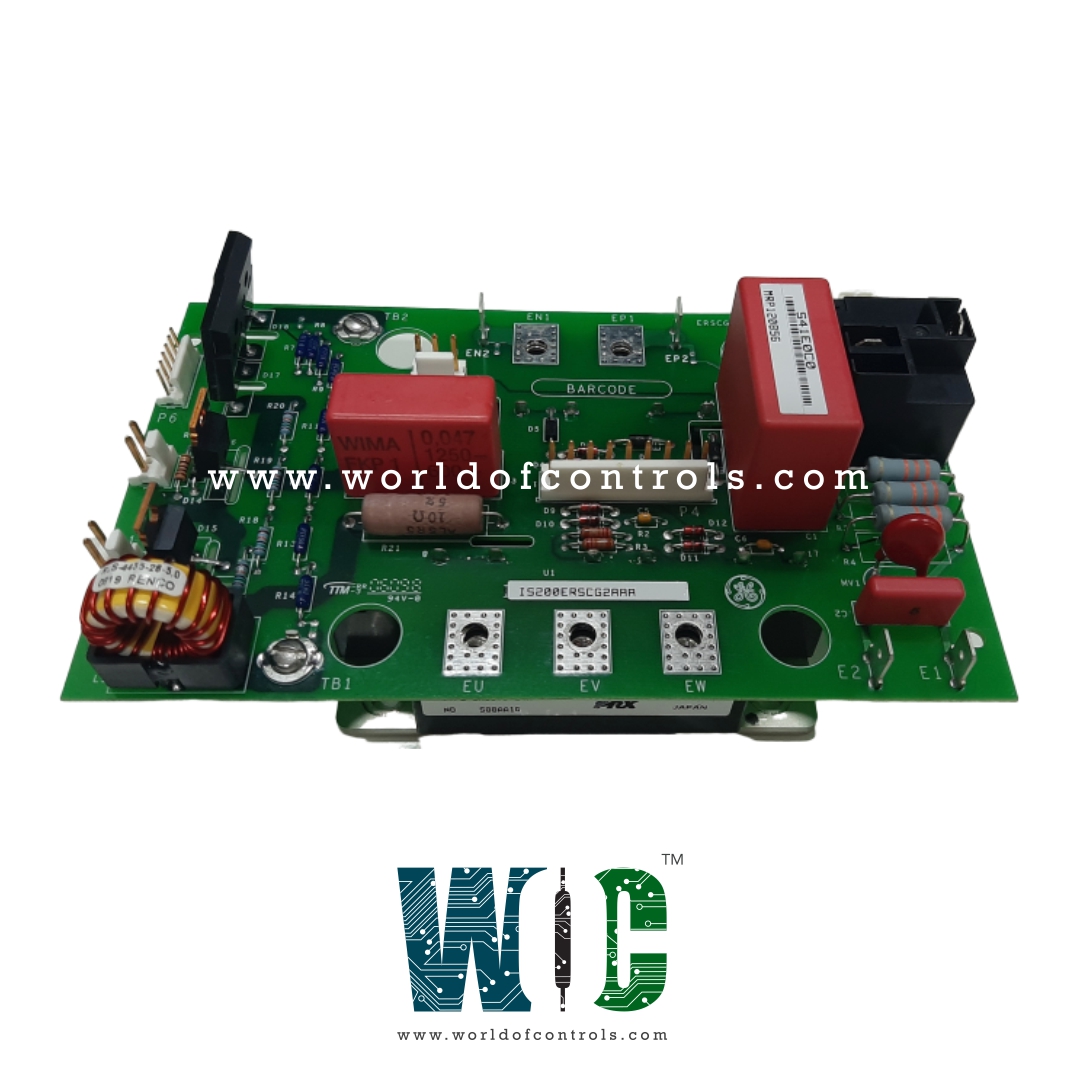
World Of Controls understands the criticality of your requirement and works towards reducing the lead time as much as possible.
IS200ERSNG1A - Exciter Regulator Dual Selector Snubber Board is available in stock which ships the same day.
IS200ERSNG1A - Exciter Regulator Dual Selector Snubber Board comes in UNUSED as well as REBUILT condition.
To avail our best deals for IS200ERSNG1A - Exciter Regulator Dual Selector Snubber Board, contact us and we will get back to you within 24 hours.
SPECIFICATIONS:
Part Number: IS200ERSNG1A
Manufacturer: General Electric
Series: EX2100e
Product Type: Exciter Regulator Dual Selector Snubber Board
Technology: Surface Mount
Analog output current: 0-20 mA
Operating Voltage Range: 24V to 250V DC
Dielectric Strength: 2.5kV AC
Current Handling Capacity: 5A to 50A
Operating Temperature Range: -40°C to +85°C
Size: 10.2 x 5.1 cm
Repair: 3-7 Day
Availability: In Stock
Weight: 2lbs
Country of Origin: United States
FUNCTIONAL DESCRIPTION:
IS200ERSNG1A is an Exciter Regulator Dual Selector Snubber Board manufactured and designed by General Electric as part of the EX2100e Series used in GE Excitation Control Systems. The Exciter Regulator Dual Selector Snubber Board is an advanced electronic component designed to enhance the performance and safety of your power system. This cutting-edge board is engineered with precision to cater to the needs of various industrial applications, ensuring efficient power regulation and protection.
EXCITATION BREAKER:
The field breaker shall comprise an electrically operated, 125Vdc, three-pole, adequately rated, AC breaker equipped with sufficient auxiliary contacts for control, monitoring, and protection functions. It shall be of the draw-out type and the operating mechanism shall be trip-free in all positions. It shall be possible to rack out the breaker in the disconnected position for LOCK OUT / TAG OUT purposes with provisions for use with a padlock. A molded case circuit breaker will not be acceptable. LED lights shall be mounted on the exterior of the breaker cabinet to indicate if the breaker is CLOSED (red) or OPEN (green). The AC breaker shall be mounted in a separate cabinet, not together with the exciter controls or thyristor bridges.
KEY FEATURES PERFORMANCE SPECIFICATIONS:
THREE-PHASE DIODE RECTIFIERS:
Diodes are used in a brushless exciter to convert AC voltage to DC, and the quantity of diodes required depends on the rating and excitation requirements of the main generator. Diodes are often connected in parallel to meet such excitation demands. In large generator applications, the quantity of diodes connected in parallel may vary anywhere from 4 to 20 diodes per phase per polarity. A good design philosophy requires that the rotating rectifier should be capable of successfully operating with 25% of its diodes out-of-service. This requirement dictates that the diodes shall be able to operate under a maximum current load of the brushless exciter. In designing a rotating machine such as an exciter, the generator field requirement or excitation requirement will be specified.
An exciter must be designed such that both the transient and continuous conditions can be handled by the exciter. After determining the machine’s rating both at continuous and at transient conditions, the number of diodes can be determined. In determining the required output capability of the exciter, the number of diodes must not include the redundancy circuits diodes. Also, the diodes employ fuses to remove any failed diodes, which typically fail in a short condition. Each diode should have a high enough reverse recovery voltage to satisfy the ceiling requirement of the exciter as well as the fuse voltage at ceiling conditions. Fuses must have enough capacity to carry steady state current as well as ceiling and surge-related currents. The function of a diode fuse is to isolate any shorted diode from the circuit to protect the remaining exciter circuits including the AC exciter armature.
WOC maintains the largest inventory of Replacement Parts for GE Excitation Turbine Control Systems. Additionally, we offer warranty-backed unused and rebuilt boards as well as board repairs for your damaged ones. For your OEM needs, our team of professionals is available around the clock. We at WOC are happy to help you with any needs you may have in terms of automation. Please contact our team by phone or email for pricing and availability on any components and repairs.
What is the operating voltage range of the Exciter Regulator Dual Selector Snubber Board?
The operating voltage range of the Exciter Regulator Dual Selector Snubber Board depends on the specific system requirements but typically falls within 24V to 250V DC. It is designed to handle voltage fluctuations while ensuring stable operation of the excitation system.
How does the snubber circuit suppress transients in the excitation system?
The snubber circuit consists of a combination of resistors and capacitors that work together to absorb and dissipate excess energy generated during switching events. It mitigates voltage spikes and ringing effects caused by inductive loads, thereby protecting semiconductor devices and other sensitive components from potential damage.
What types of excitation systems are compatible with this board?
The Exciter Regulator Dual Selector Snubber Board is compatible with brushless and static excitation systems used in synchronous generators. It can be integrated with both DC and AC excitation control systems, ensuring seamless redundancy and transient suppression in various power generation setups.