SPECIFICATIONS
Part No.: IS200ERIOH1AAA
Manufacturer: General Electric
Country of Manufacture: United States of America (USA)
Product Type: Exciter Regulator I/O Board
Availability: In Stock
Series: EX2100
Functional Description
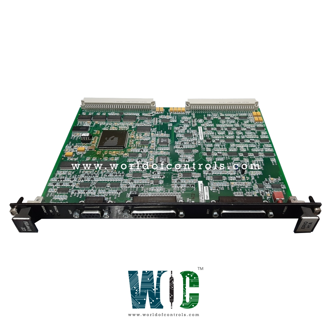
IS200ERIOH1AAA is an exciter regulator I/O board developed by GE. It is part of the EX2100 series. The Exciter Regulator Main I/O Board (ERIO) serves as a vital component within the EX2100 regulator control systems, catering to both simplex and redundant configurations. Its primary function lies in providing the necessary I/O interface for customer and system I/O operations, facilitating seamless communication and control within the system architecture.
Role in Simplex Applications
- In simplex applications, the board is mounted within the Exciter Regulator Backplane (ERBP). Here, it assumes the critical task of interfacing customer I/O signals for other essential components such as the Exciter PT/CT Terminal Board (EPCT) and the Exciter Contact Terminal Board (ECTBG2).
- Additionally, it handles system I/O signals for components like the Exciter Regulator Dynamic Discharge board (ERDD) and the Exciter Regulator Options Card (EROC), ensuring smooth functionality and integration within the simplex configuration.
Redundant Configurations
- In redundant configurations, the board continues to play a pivotal role by providing seamless I/O interface functionality, albeit within a redundant system setup.
- Its role remains consistent, ensuring reliable communication and control between various system components, thereby enhancing system robustness and fault tolerance.
Features
- Form Factor and Connectors: Adopts a single-slot double-height (6U) form factor and features both P1 and P2 backplane connectors, each serving distinct purposes in the interface hierarchy.
- Functionality of Connectors: While the P1 connector serves as a slave interface for communication with other system components, the P2 connector acts as the primary interface for I/O signals and connections with other backplane-mounted boards.
- External Connections: The faceplate integrates two 25-pin sub-D connectors, strategically positioned to establish direct connections with external components such as the ECTB and EPCT terminal boards.
- Enhanced Versatility: The dual-connector setup and external connectors enhance the versatility, enabling seamless interaction with various system elements and external components.
Application Data
- Form Factor and Connectivity: Boasts a single-slot double-height (6U) form factor, ensuring compatibility and efficient utilization of space within the system setup. Equipped with both P1 and P2 96-pin backplane connectors, the board facilitates robust connectivity and communication within the system.
- Interface with Terminal Boards: Functionality extends to direct interaction with terminal boards such as the Exciter Contact Terminal Board and Exciter PT/CT Terminal Board. This interaction is facilitated through two 25-pin sub-D receptacle connectors located on the ERIO faceplate, ensuring seamless integration and communication between the ERIO and these essential components.
- Diagnostic Capabilities: Furthermore, it enhances diagnostic capabilities through the inclusion of a 9-pin sub-D receptacle connector labeled "TEST" on its faceplate. This connector serves as a diagnostic interface, enabling the monitoring and troubleshooting of system performance and functionality.
The WOC team is always available to help you with your EX2100 requirements. For more information, please contact WOC.
Frequently Asked Questions
What is IS200ERIOH1AAA?
It is an exciter regulator I/O board developed by GE under the EX2100 series.
How can a system reset be initiated?
A system reset switch, labeled RESET, is located near the bottom of the faceplate. Pressing this switch, although recessed for protection, initiates a system reset.
What does the POWER LED indicate?
It illuminates when power is applied to the board, providing a visual indication of its operational status.
What does the OK LED signify?
The LED indicates that the board is functioning correctly, reassuring users of its proper operation within the system.
What does the ACTIVE LED indicate?
The LED signals when the board is selected as the master controller within the system, aiding in system monitoring and control.
