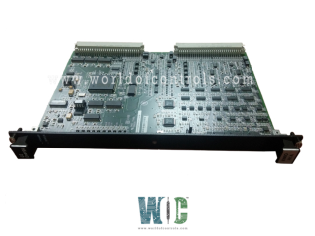
World Of Controls understands the criticality of your requirement and works towards reducing the lead time as much as possible.
IS200EMIOH1AEB - Exciter Main I/O Board is available in stock which ships the same day.
IS200EMIOH1AEB - Exciter Main I/O Board comes in UNUSED as well as REBUILT condition.
To avail our best deals for IS200EMIOH1AEB - Exciter Main I/O Board, contact us and we will get back to you within 24 hours.
SPECIFICATIONS:
Part Number: IS200EMIOH1AEB
Manufacturer: General Electric
Series: EX2000
Product Type: Exciter Main I/O Board
Number of channels: 12
Input span: 4-20 mA
Technology: Surface Mount
Common Mode Voltage Range: ±5 V
Maximum Lead Resistance: 15Ω
Analog output current: 0-20 mA
Operating temperature: -30 to 65 °C
Size: 8.26 cm high x 4.19 cm
Repair: 3-7 Day
Availability: In Stock
Country of Origin: United States
Manual: GEI-100453
FUNCTIONAL DESCRIPTION:
IS200EMIOH1AEB is an Exciter Main I/O Board manufactured and designed by General Electric as part of the EX2000 Series used in GE Excitation Control Systems. The Main I/O board is a single-slot, double-height VME-style board that mounts in the control rack. EMIO handles the I/O from the EPCT, ECTB, EACF, and EXTB terminal boards. The I/O includes PT and CT signals. Contact inputs, output relay drivers, and pilot trip relay drives. It also sends logic-level gate pulse signals over the backplane to the ESEL board, which sends them to EGPA in the power conversion cabinet. EMIO handles inputs and outputs from several I/O boards that are cabled to the control rack. Gate command outputs to ESEL and the flashing and de-excitation outputs to EXTB are shown in the following figure. Commands from EMIO to ESEL are transferred over the backplane.
APPLICATION DATA:
The layout of the EMIO board with LEDs is shown in the first figure, the EMIO Board. The Power LED is connected to the 5 V dc power, and the Status LED is connected to the IMOK output from the FPGA. There are no jumpers, fuses, or cable connectors on the board. All cabling from the I/O boards is connected to the control backplane (EBKP). Connector P1 provides communication with the other control boards over the backplane, while P2 provides the interface to the I/O signals through cable connectors located at the lower part of EBKP.
WOC has the largest stock of GE Excitation Control System Replacement Parts. We can also supply unused and rebuilt backed-up with a warranty. Our team of experts is available round the clock to support your OEM needs. Our team of experts at WOC is happy to assist you with any of your automation requirements. For pricing and availability on any parts and repairs, kindly get in touch with our team by phone or email.
What is the Exciter Main I/O Board?
The Exciter Main I/O Board is a crucial component in the exciter system of machinery or equipment. It serves as the central interface for input and output signals, facilitating communication between various parts of the exciter system.
What are the primary functions of the Exciter Main I/O Board?
The main functions include receiving input signals from sensors or control devices, processing these signals, and generating output signals to control actuators or other components in the exciter system. It also manages communication between the exciter system and external systems or devices.
What types of signals does the Exciter Main I/O Board support?
The board typically supports various types of signals, including analog signals (voltage or current), digital signals (binary), and communication protocols such as RS-232, RS-485, or Modbus
.