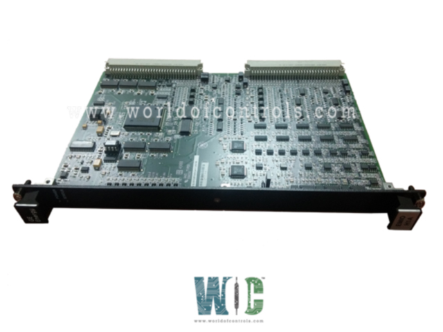
SPECIFICATIONS
Part No.: IS200EMIOH1ADA
Manufacturer: General Electric
Country of Manufacture: United States of America (USA)
Size: 15.9 cm high x 10.2 cm wide
Technology: Surface-mount
Temperature Operating: -30 to 65oC
Product Type: Exciter Main I/O Board
Availability: In Stock
Series: EX2100
Functional Description
IS200EMIOH1ADA is an Exciter Main I/O Board developed by GE. It is a part of the EX2100 excitation system. It is designed to fit seamlessly within the control rack setup. This single-slot, double-height VME-style board serves as the interface for various terminal boards, including the EPCT, ECTB, EACF, and EXTB. Its primary function revolves around handling a diverse range of input and output signals, encompassing PT (pressure transmitter) and CT (current transformer) signals, contact inputs, output relay drivers, and pilot trip relay drives.
Features
- Gate Pulse Transmission: One of the board's critical features is its ability to transmit logic-level gate pulse signals via the backplane to the ESEL (Exciter Selector) board. These signals are subsequently relayed by the ESEL board to the EGPA (Exciter Gate Pulse Amplifier), which is housed in the power conversion cabinet. This pathway is essential for ensuring the synchronization and coordination of operations within the control system. The gate pulse signals help regulate and manage the exciter's function, contributing to the optimal performance of the power generator.
- Cabling and Signal Integration: All cabling from the various I/O boards consolidates at the EBKP (Exciter Backplane). This centralized approach simplifies the management of the complex network of signals throughout the control system, improving system organization and reducing potential points of failure.
- Connector P1: This connector facilitates communication between the I/O boards and other control boards, enabling the transfer of data over the backplane. This ensures that the board can seamlessly interact with other system components to manage signals effectively.
- Connector P2: Located at the lower part of the EBKP, this connector is responsible for transmitting and receiving I/O signals. The cables connected here allow for the smooth integration of these signals into the broader control system, helping to optimize overall performance and signal transmission.
Board Replacement Procedure
- Ensure De-Energization: Before any work, verify that the exciter has been completely de-energized to prevent any electrical hazards.
- Safety Checks: Open the control cabinet door and perform electrical circuit tests to confirm that all circuits are inactive and power is effectively turned off. This precautionary measure ensures personal safety before handling any components.
- Remove the Existing EMIO Board: Loosen the screws located at the top and bottom of the EMIO board's faceplate, near the ejector tabs. These screws are designed to remain attached to the faceplate. Raise the ejector tabs to unseat the module securely. Using both hands, carefully pull the board out from the rack, ensuring gentle handling to avoid damage.
- Insert the Replacement Board: Slide the replacement board into the designated slot within the rack, ensuring alignment with the guide rails.
- Seat the Board: Begin seating the board by applying firm pressure simultaneously to the top and bottom of the faceplate using your thumbs. Ensure even pressure distribution for proper alignment.
- Secure the Board: Finish seating the board securely by starting and then tightening the screws at both the top and bottom of the faceplate. Tighten the screws evenly to ensure that the module is seated securely and squarely within the rack slot.
Application Data
- The layout of the EMIO board includes LEDs. The Power LED is linked to the 5 V DC power source, providing a visual indication of power status. The Status LED is connected to the IMOK output from the FPGA, serving as an indicator of the operational status of the board. No jumpers, fuses, or cable connectors are present on the board.
- All cabling from the Input/Output (I/O) boards is connected to the control backplane. Connector P1 facilitates communication with other control boards over the backplane, enabling data exchange and coordination between various components of the control system.
- Connector P2 serves as the interface to the I/O signals, allowing connectivity with cable connectors situated at the lower part of the EBKP. This arrangement enables the transmission of input and output signals between the board and external devices or sensors.
The WOC team is always available to help you with your EX2100 requirements. For more information, please contact WOC.
Frequently Asked Questions
What is IS200EMIOH1ADA?
It is an Exciter Main I/O Board developed by GE under the EX2100 series.
What is the purpose of the board?
The EMIO board handles input/output (I/O) signals from various terminal boards in the control system, facilitating communication between different components and relaying signals to the exciter.
How is the board connected to the control system?
All cabling from the I/O boards is connected to the control backplane (EBKP). Connector P1 on the EMIO board provides communication with other control boards over the backplane, while P2 interfaces with I/O signals through cable connectors.
Can the board be replaced while the exciter is running in a redundant control system?
Yes, it is possible to replace a failed while the exciter is operational in a redundant control system. However, certain precautions must be taken to ensure a smooth replacement process without causing system shutdown.
