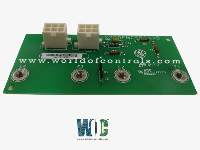
World Of Controls understands the criticality of your requirement and works towards reducing the lead time as much as possible.
IS200EMCSG1AAB - Multibridge Conduction Sensor Card is available in stock which ships the same day.
IS200EMCSG1AAB - Multibridge Conduction Sensor Card comes in UNUSED as well as REBUILT condition.
To avail our best deals for IS200EMCSG1AAB - Multibridge Conduction Sensor Card, contact us and we will get back to you within 24 hours.
Part No.: IS200EMCSG1AAB
Manufacturer: General Electric
Country of Manufacture: United States of America (USA)
Temperature: -30 to 65oC
Connectors: Six-plug
Dimensions: Length 4.35 Inches, Width: 2 Inches
Number of Conduction Sensors: 4, E1-E4
Product Type: Exciter Multibridge Conduction Sensor Card
Availability: In Stock
Series: Mark VI
IS200EMCSG1AAB is an Exciter Multibridge Conduction Sensor Card developed by GE. It is a part of Mark VI control system. It is used in exciter systems to monitor conduction within the exciter system, detecting irregularities, and ensuring optimal performance. Its advanced sensor technology and reliable power supply connectivity make it an essential component for exciter system functionality. This card features advanced capabilities for detecting and analyzing conduction across various points within the exciter.
The WOC team is always available to help you with your Mark VI requirements. For more information, please contact WOC.
What is IS200EMCSG1AAB?
It is an Exciter Multibridge Conduction Sensor Card developed by GE under the Mark VI series.
What drives the RS-232C serial port?
The RS-232C serial port is driven by a computer chip known as a Universal Asynchronous Receiver/Transmitter (UART). This chip is responsible for sending data in the form of 8-bit bytes over the serial port. Each byte of data is preceded by a start bit, followed by 8 data bits, an optional parity bit, and one or two stop bits.
What is the significance of transmission baud rate?
The transmission baud rate indicates the speed at which bits are transmitted over the serial port, measured in bits per second. It determines how quickly data can be sent and received between devices.
What is the purpose of parity in serial communication?
Parity provides a mechanism to detect errors in the transmitted data. An additional parity bit is added to each byte of data to ensure that the total number of bits in the byte, including the parity bit, is either even or odd.