SPECIFICATIONS
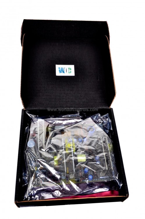
Part No.: IS200EGPAG1ABD
Manufacturer: General Electric
Country of Manufacture: United States of America (USA)
Temperature Operating: -30 to 65oC
Product Type: Exciter Gate Pulse Amplifier Board
Availability: In Stock
Series: EX2100
Functional Description
IS200EGPAG1ABD is an Exciter Gate Pulse Amplifier Board developed by GE. It is a part of the EX2100 control system. It manages gate commands received from the ESEL and controlling the gate firing of up to six SCRs on the Power Bridge. Additionally, it serves as the interface for various feedback mechanisms, including current conduction feedback, and facilitates monitoring of bridge airflow and temperature.
Features
- The board is equipped with a comprehensive set of functionalities, as depicted in the following functional model diagram. It relies on a nominal 125 V DC power source from the EPDM, which powers an onboard DC/DC converter. This converter ensures consistent power delivery for SCR gating operations across a wide range of input supply voltages.
- Visual indicators in the form of LEDs are incorporated into the board to provide users with real-time status updates. These LEDs illuminate to signify the status of various aspects such as the EGPA power supply, input gate commands received from the ESEL, EGPA outputs to the SCRs, currents flowing into the bridge, status of the line filter, rotation of the cooling fan, bridge temperature, as well as any alarms or fault conditions that may arise during operation.
Sensor Inputs
- Conduction Current Sensing: Conduction currents on all three phases of the bridge input are sensed using Hall Effect sensors located on the EXCS boards. The EGPA provides power to these sensors and receives signals indicating the status of current flow through each leg of the three-phase bridge input. These signals are conditioned by the EGPA and transmitted to the controller via J9-J10 connectors.
- Bridge Temperature Sensing: Bridge temperature is monitored using an RTD (thermistor) sensor input or temperature switch input. For new exciters, only the RTD input is utilized, with jumpers on the EGPA disabling the temperature switch inputs. In retrofitting scenarios, where an EX2100 control is added to an existing bridge, temperature switch inputs are utilized to interface with switches already mounted on the bridge. Both RTD and temperature switch inputs are connected at J13.
- Airflow Sensor (Fan Rotation) Monitoring: Loss of fan cooling in the bridge is detected through airflow sensors. Up to four fans can be connected to the EGPA via J12 connectors. The EGPA accepts either a pulsed or dry-contact, normally open sensor input from the fans. The mode of signal detection is configured through berg jumpers JP2-JP4.
- Line Filter Fuse Failure Sensing: Failure of the line filter fuse is sensed at J14 on the EGPA. This sensor input accepts a single, normally closed, dry contact input, providing essential feedback on the health of the line filter.
I/O Connections
- The EGPA board facilitates crucial connections between the control system and the silicon-controlled rectifiers (SCRs) in the power bridge, ensuring efficient control and monitoring of the excitation process.
- SCR Gate Outputs: Individual SCR gate outputs are wired to the bridge through two-pin connectors, labeled J1 through J6. Each connector corresponds to a specific SCR in the bridge. For instance, J1 connects to SCR1, J2 to SCR2, and so forth. The pin configuration for these connectors is standardized as follows:
- Pin 1- SCR Cathode
- Pin 2- SCR Gate
The numbering convention aligns with the connector and SCR number. For example, J3-1 corresponds to the Cathode connection for SCR3.
- Power Supply Connection: The power supply for the gate outputs is provided via connector J8, which consists of two pins. The power supply operates at a nominal 125 V dc (with a range of 80-140 V dc) and is configured.
- Pin 1- Power Supply Input, 125 V dc
- Pin 2- Power Supply Common, PSCOM
- These connections ensure reliable power distribution to the SCR gate outputs, facilitating precise control of the excitation process.
The WOC team is always available to help you with your EX2100 requirements. For more information, please contact WOC.
Frequently Asked Questions
What is IS200EGPAG1ABD?
It is an Exciter Gate Pulse Amplifier Board developed by GE under the EX2100 series.
How are SCR gate outputs connected to the bridge?
Individual SCR gate outputs are connected via two-pin connectors labeled J1 through J6. Each connector corresponds to a specific SCR in the bridge. For example, J1 connects to SCR1, J2 to SCR2, and so on. The pin configuration for these connectors includes the SCR cathode and gate.
What is the power supply configuration for the gate outputs?
The power supply for the gate outputs is provided through connector J8, with two pins. Pin 1 serves as the power supply input, delivering a nominal 125 V dc (with a range of 80-140 V dc). Pin 2 functions as the power supply common (PSCOM).
How are airflow sensors and temperature sensors connected to the board?
Airflow sensors (fan rotation) and temperature sensors are connected to designated terminals on the EGPA board. Airflow sensors are connected through J12, while temperature sensors are connected to J13. These connections enable the monitoring of critical operating parameters in the power bridge.
