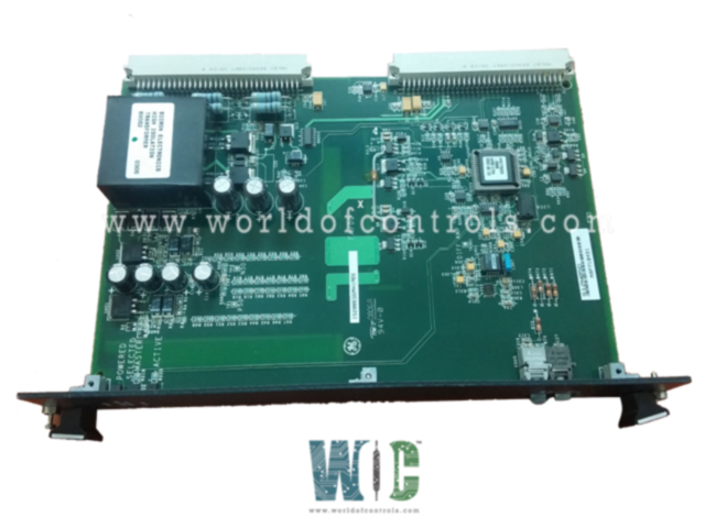
SPECIFICATIONS
Part No.: IS200EGDMH1AAB
Manufacturer: General Electric
Country of Manufacture: United States of America (USA)
Size: 15.9 cm high x 10.2 cm wide
Temperature: -30 to + 65oC
Technology: Surface-mount
Product Type: Exciter Ground Detector Module
Availability: In Stock
Series: EX2100
Functional Description
IS200EGDMH1AAB is an Exciter Ground Detector Module developed by GE. It is a part of the EX2100 excitation system. The Ground Detection Module serves as an integral component within the EX2100 Excitation Control system, designed to ensure the reliability and safety of generator field circuits by detecting potential ground faults. This module adopts a double slot, double height (6U) form factor, fitting into the Exciter Power Backplane rack (EPBP) as part of the system's architecture. Its integration into the system's architecture, along with its collaboration with the EXAM module, contributes significantly to the system's ability to promptly identify and address ground fault issues, thereby enhancing operational safety and reliability within generator systems.
Features
- Field Ground Detection: The primary function of the module is to detect field leakage resistance between any point in the generator field circuit and ground. This detection capability covers both the alternating current (ac) and direct current (dc) sides of the circuit, aiming to identify any abnormal leakage that could potentially pose a safety hazard or compromise system integrity.
- System Configuration: In a simplex system configuration, a single EGDM module is utilized for ground detection. However, in a redundant system setup aimed at enhancing reliability, three EGDM modules are employed, further ensuring robust ground fault detection capabilities across the generator field circuit.
- Module Location: The location within the system is indicated in Figure 1, likely outlining their placement within the system's rack or chassis for optimized functionality and accessibility during operation and maintenance.
- EXAM Module Interaction: The Ground Detection Module collaborates with the EXAM (EXcitation AMplifier) module, which functions as an attenuator sensing the voltage across the ground sense resistor. This voltage signal is transmitted using a specialized nine-conductor cable. The EXAM module itself is housed within the High Voltage Module situated in the Auxiliary Panel.
Fiber-optic connectors
- Fiber-optic connectors play a crucial role in ensuring the transmission of signals within systems, especially in scenarios where reliability, high data rates, and minimal signal interference are paramount. Within the context of the EGDM (Ground Detection Module), two distinct fiber-optic connectors, U201 and U305, facilitate signal transmission between the module and the EISB (Excitation ISB) board.
- Lower Fiber-Optic Connector (U201): U201 serves as the connector responsible for carrying the oscillator signal from the EISB board to the Ground Detection Module. This connector utilizes a Hewlett Packard HFBR2528 receive connector, specifically designed to receive optical signals reliably.
The HFBR2528 receive connector ensures efficient reception of the oscillator signal, providing a robust link for the transmission of this specific signal from the EISB board to the EGDM module.
- Upper Fiber-Optic Connector (U305): Conversely, U305 functions as the connector responsible for sending the sense resistor signal from the EGDM module to the EISB board. This connector employs a Hewlett Packard HFBR1528 transmit connector, specially designed for transmitting optical signals.
- The HFBR1528 transmit connector ensures efficient and reliable transmission of the sense resistor signal, completing the bidirectional communication between the EGDM module and the EISB board.
LED Indicators
- Upper LED - Power Status Indicator: The uppermost LED serves as an indicator to denote the application of power to the board from the backplane. When illuminated, this LED signifies that the board is receiving power from the backplane, confirming its operational power supply.
- Middle LED - Master Selection Indicator: Positioned in the middle, this LED serves as an indicator for the master selection status of the board within the system hierarchy. When this LED is illuminated, it indicates that this specific board has been selected as the master within the system configuration.
- Lower LED - Master Status and 50 Volt Signal Indicator: The bottom LED serves a dual purpose
- It signifies that the board is functioning as the master within the system.
- Additionally, it indicates that the master board is actively sending a 50-volt signal, potentially related to its operational functionality or specific signal transmission related to ground detection operations.
The WOC team is always available to help you with your EX2100 requirements. For more information, please contact WOC.
Frequently Asked Questions
What is IS200EGDMH1AAB?
It is an Exciter Ground Detector Module developed by GE under the EX2100 series.
Is it possible to replace a failed EGDM while the exciter remains operational in a redundant control system?
Yes, in a redundant control system, it's feasible to replace a failed EGDM without interrupting the exciter's operation. The system is designed to allow this replacement while maintaining exciter functionality.
What happens if a failed module is left in place in a redundant system?
There's an option to leave the failed EGDM within the system while the exciter continues to operate on the remaining modules. This approach ensures continuous operation without reliance on the failed module.
Are there consequences in the event of multiple failures in a redundant control system?
In the unlikely occurrence of a second failure in another control section, leading to a total of two EGDM failures, the exciter is programmed to initiate a shutdown sequence. This safety feature aims to prevent potential risks or hazards due to multiple failures within the system.
