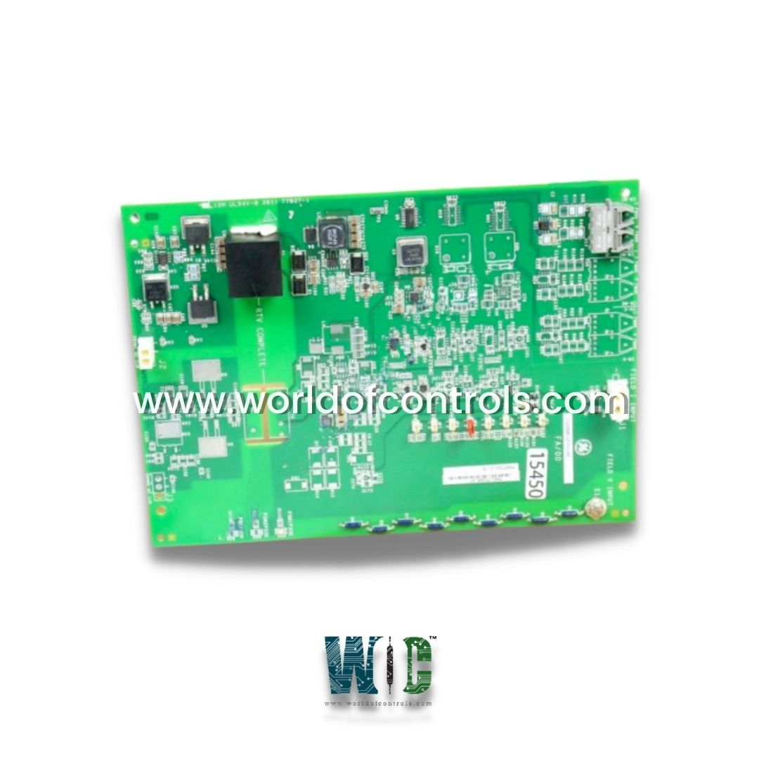
IS200EDFFH3A - I/O Terminal Board

IS200EDFFH3A - I/O Terminal Board IS200EDFFH3A - I/O Terminal Board

World Of Controls understands the criticality of your requirement and works towards reducing the lead time as much as possible.

IS200EDFFH3A - I/O Terminal Board is available in stock which ships the same day.

IS200EDFFH3A - I/O Terminal Board comes in UNUSED as well as REBUILT condition.

To avail our best deals for IS200EDFFH3A - I/O Terminal Board, contact us and we will get back to you within 24 hours.

SPECIFICATIONS

Part No.: IS200EDFFH3A
Manufacturer: General Electric
Function: I/O Terminal Board
Series: EX2100e
Part Specific Manual GEI-100770
Product Type: PCB
Country of Manufacture: United States (USA)

Functional Description

IS200EDFFH3A is an I/O Terminal Board developed by GE. It is a part of EX2100e excitation system. This I/O Terminal Board serves a critical role in the system by providing the necessary connections for both digital and analog inputs and outputs, facilitating the seamless exchange of signals and data between various components. The primary function of the I/O Terminal Board is to serve as an interface between the EX2100e excitation system and external devices or systems. It enables communication with sensors, actuators, control devices, and other equipment involved in the excitation process. The board incorporates a range of input and output terminals to accommodate different types of signals and connections. One of the key features of the I/O Terminal Board is its capability to handle both digital and analog inputs and outputs. Digital inputs typically include signals such as status indicators, switches, or contact closures, while analog inputs deal with continuous signals such as voltage or current measurements. Similarly, digital outputs can control relays, alarms, or other devices, while analog outputs are utilized for precise control and modulation of signals. The board also includes various integrated features that enhance its functionality. These features can include voltage and current sensing capabilities, which allow for accurate measurement and monitoring of electrical parameters in the system. Relay outputs provide the ability to control external devices based on specific conditions or triggers, expanding the control capabilities of the excitation system. To aid in troubleshooting and maintenance tasks, the I/O Terminal Board incorporates diagnostic LEDs. These LEDs provide visual indicators to quickly identify the status or potential issues related to specific inputs or outputs. By observing the LED patterns, operators and technicians can efficiently diagnose problems and take appropriate corrective actions.

Features

  • The board offers a range of features designed to measure voltages and field currents at the silicon-controlled rectifier (SCR) bridge. Its primary purpose is to interface with the EAUX or Excitation Control Auxiliary Interface through a high-speed fiber-optic cable link, enabling efficient communication and data transfer.
  • The board comes in three different group variations, one of which is the H3 group variation model. This particular model is designed to operate in a simplex system, ensuring reliable performance in a non-redundant setup.
  • Within the High Voltage Interface module, the EDFF board plays a crucial role. It receives a low-voltage output signal, measured in millivolts, from a current shunt in the power conversion module. This output signal is then processed through a differential amplifier integrated. The resulting signal provides essential voltage feedback and direct current (DC) currents to the control systems, allowing for precise control and regulation of the silicon-controlled rectifiers.
  • To facilitate voltage feedback and field current feedback, the board features V-F or voltage-to-frequency converter circuits. These circuits accurately convert voltage signals to corresponding frequency signals, providing valuable feedback information for the control systems. The EDFF board supports up to three redundant sections, labeled controllers C, M1, and M2. This redundancy ensures system reliability and fault tolerance by allowing the use of backup controllers in case of failures in primary components.
  • The high-speed fiber-optic cable link enables rapid data transfer between the EDFF board and the Excitation Control Auxiliary Interface, enhancing the overall efficiency and responsiveness of the system. The use of fiber-optic technology ensures reliable and noise-free communication, even in electrically noisy environments.

Characteristics

  • Interfaces: Designed to interface with the Auxiliary Interface, allowing for seamless communication and data exchange between the board and other components of the system. This interface enables the board to receive and transmit signals, measurements, and control commands necessary for its operation.
  • Mounting Location: Typically installed within the Auxiliary Cabinet, which is a dedicated enclosure designed to house auxiliary components and modules. By locating the board in the Auxiliary Cabinet, it can be conveniently integrated into the overall system architecture, ensuring easy access and proper organization of components.
  • Power Supply: Requires a power supply of 28 VDC (volts direct current) to operate effectively. This voltage level is critical to ensure proper functionality and performance of the board, allowing it to carry out its measurement and control tasks accurately and reliably.
  • Redundancy Mode: Operates in a simplex redundancy mode. Simplex redundancy means that the board functions as a single unit without backup or redundant components. While it may not offer inherent redundancy, the simplicity of the system setup can make it easier to configure, maintain, and troubleshoot.
  • By operating in simplex mode, the board may be suitable for applications where redundancy is not a critical requirement or where the associated costs and complexity of implementing a redundant system may not be justified.

World of Controls has the most comprehensive collection of GE EX2100e components. Please contact WOC as soon as possible if you require any extra information.


Frequently Asked Questions


What is IS200EDFFH3A?
It is an I/O Terminal Board developed by GE.

What is the H3 group variation model of the board?
The H3 group variation model of the board is one of the three different group variations available, and it can only operate in a simplex system.

Where is the EDFF board used within the High Voltage Interface module?
It is used within the High Voltage Interface module to provide voltage feedback and DC currents to the controls.

What is the role of the current shunt in the power conversion module?
The current shunt in the power conversion module produces a mV output signal, which is received by a differential amplifier on the board.