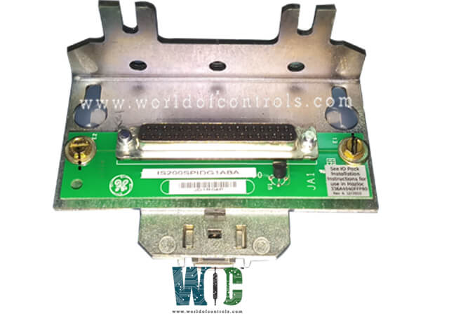
SPECIFICATIONS
Part No.: IS200EDEXG1BAA
Manufacturer: General Electric
Country of Manufacture: United States of America (USA)
Size: 33.02 cm high x 10.16 cm wide
Temperature: -30 to 65 oC
Product Type: Exciter De-Excitation Control Board
Availability: In Stock
Series: EX2100e
Functional Description
IS200EDEXG1BAA is an Exciter De-Excitation Control Board developed by GE. It is part of the EX2100e excitation system. The Exciter De-Excitation control board (EDEX) is a component within the de-excitation module. Its primary function is to dissipate stored energy from the generator field during emergency shutdowns, especially when the field breaker or contactors are opened.�
Features
- SCR Firing: The board is responsible for controlling the firing of Silicon Controlled Rectifiers. These SCRs are crucial for managing the flow of current and dissipating energy from the generator field effectively.
- Conduction Sense Feedback: It provides feedback mechanisms to sense the conduction status of the SCRs. This feedback loop ensures that the de-excitation process operates smoothly and efficiently.
- Voltage Retention: Even in the event of a power failure, the EDEX board maintains voltage retention capabilities. This feature ensures that the de-excitation process continues uninterrupted, enhancing system reliability during critical situations.
- Initiation by EMIO: De-excitation is initiated by the Excitation Module Input/Output (EMIO) board. When triggered, the EMIO board sends signals to the EXTB board, which then opens the designated contactor or breaker to begin the de-excitation process.
- Signal Transfer and SCR Firing: The board, after opening the contactor or breaker, transfers de-excitation signals from auxiliary contacts to the SCR firing circuits. This sequence of actions ensures that the SCRs are triggered appropriately to dissipate the stored energy from the generator field.
Voltage Hold-Up Circuit
- Retention of Voltage Levels: The primary purpose of the Voltage Hold-Up Circuit is to retain voltage levels on both the positive and negative 24 V DC rails. By doing so, it ensures that essential components, such as the firing circuitry and control mechanisms, remain powered even in the event of a total power failure.
- Emergency SCR Firing: In situations where there is a complete loss of power, the retained voltage on the 24 V DC rails enables the board to initiate the firing of the SCR (Silicon Controlled Rectifier). This action is crucial for effectively dissipating the stored energy from the generator field during emergency shutdowns.
- Wetting of External De-Excitation Contacts: Voltage Hold-Up Circuitry provides the necessary voltage for wetting the external de-excitation contacts. This ensures that the contacts remain functional and responsive, facilitating the firing command required for de-excitation after a power failure.
Conduction Sensors
- Detection Principle: The Conduction Sensors utilize Hall Effect sensors, which are semiconductor devices that respond to magnetic fields. These sensors are strategically positioned at the top edge of the EDEX board. When current flows through the field circuit, it generates a magnetic field that is detected by the Hall Effect sensors.
- Mechanical Ring: A mechanical ring, located within the field circuit, serves to couple magnetic flux to the Hall Effect sensors. This ensures that the sensors accurately detect the presence and magnitude of current flow in the circuit.
- Bipolar Current Detection: The sensor circuits 1 and 2 are designed to detect bi-polar current flow, meaning they can sense current in both directions. This capability allows the EDEX board to effectively monitor variations in current flow, enabling precise control and management of the de-excitation process.
- Current Sense Signals: The detected current signals, represented as M1 and M2, are then transmitted to the EXTB board. From there, these signals are further processed and utilized for control purposes, ultimately influencing the de-excitation operation based on the detected current levels.
- LED Indicators: Features two red LEDs that serve as status indicators for both current sense circuits. These LEDs illuminate whenever current flow is detected, providing visual feedback to operators and indicating the operational status of the Conduction Sensors.
The WOC team is always available to help you with your EX2100e requirements. For more information, please contact WOC.
Frequently Asked Questions
What is IS200EDEXG1BAA?
It is an exciter de-excitation control board developed by GE under the EX2100e series.
How is power supplied to the board?
Power is supplied through connectors J1 and J2.
What connects the board to the external de-excitation signal?
The cable carrying the de-excitation signal connects to connector J8 on the board.
What are the stab connectors E1B through E12 used for?
Stab connectors E1B through E12 are used for wire jumpers to select the break over diodes and current limiting resistors for the voltage and size of the SCR.
How is the SCR anode connected on the board?
Stab connector E1A is wire jumpered to the SCR anode, establishing the connection for the SCR.
