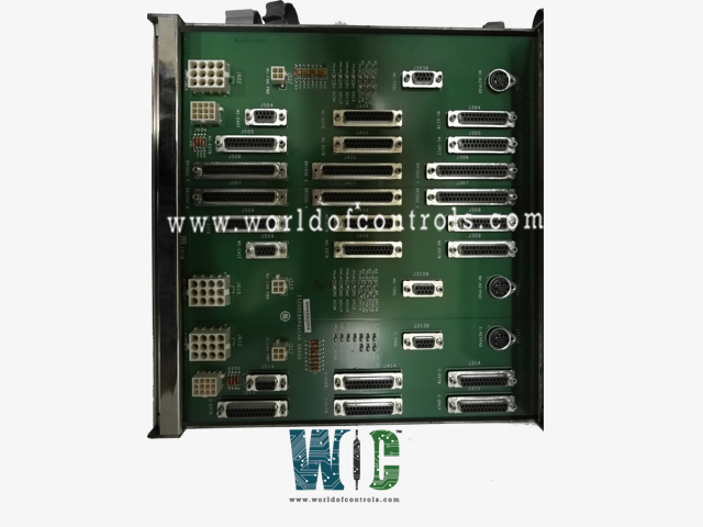
IS200EBKPG1CAA - Exciter Backplane Board

IS200EBKPG1CAA - Exciter Backplane Board IS200EBKPG1CAA - Exciter Backplane Board

World Of Controls understands the criticality of your requirement and works towards reducing the lead time as much as possible.

IS200EBKPG1CAA - Exciter Backplane Board is available in stock which ships the same day.

IS200EBKPG1CAA - Exciter Backplane Board comes in UNUSED as well as REBUILT condition.

To avail our best deals for IS200EBKPG1CAA - Exciter Backplane Board, contact us and we will get back to you within 24 hours.

SPECIFICATIONS

Part No.: IS200EBKPG1CAA
Manufacturer: General Electric
Country of Manufacture: United States of America (USA)
Number of channels: 24
Temperature: 0 to 60°C
Size: 26.04 cm high x 1.99 cm wide x 18.73 cm deep
Product Type: Exciter Backplane Board
Availability: In Stock
Series: EX2100

Functional Description

IS200EBKPG1CAA is an Exciter Backplane Board developed by GE. It is a part of EX2100 excitation system. The Exciter Back Plane (EBKP) is an integral component of the control module, serving as the backbone for the control boards and providing connectors for I/O terminal board cables. This critical unit consists of three distinct sections, namely M1, M2, and C, each catering to specific functionalities within the system.

Configurationand Mounting

  • M1 and M2 Sections: These sections boast independent power supplies and accommodate an array of essential control boards, including ACLA, DSPX, EISB, EMIO, and ESEL boards.
  • Section C: Specifically designated for Section C, this area hosts the DSPX, EISB, and EMIO boards, tailoring functionality to meet unique requirements.
  • Mounting and Cooling: The EBKP board is securely mounted within a rack, which houses the assortment of control boards. Additionally, to ensure optimal operating conditions, two cooling fans are strategically positioned at the top of the rack, providing necessary ventilation and heat dissipation.

Testpoints

  • The Exciter Back Plane incorporates three sets of testpoints, each tailored for specific sections: M1, M2, and C. These testpoints serve as invaluable diagnostic tools, enabling technicians to monitor and analyze system performance effectively.
  • Group Configuration: The M1 section features a dedicated group of seven testpoints, including two differential points, meticulously designed to facilitate diagnostics and troubleshooting procedures.
  • Toolbox Integration: Leveraging advanced software capabilities, technicians utilize the toolbox to configure and customize these testpoints according to specific diagnostic requirements. This integration enhances diagnostic precision and efficiency, streamlining the identification and resolution of potential issues.

Exciter Gate Pulse Amplifier Connector

  • The Exciter Gate Pulse Amplifier (EGPA) connector interface comprises six connectors, designated as follows: J306, J307, J406, J407, J506, and J507. These connectors serve as the interface points for up to six EGPA boards, each intended to be controlled by the Exciter Selector (ESEL) board.
  • Connector Allocation:
    • J306 and J307 correspond to PCMs (bridges) 1 and 2, respectively.
    • J406 and J407 correspond to PCMs (bridges) 3 and 4, respectively.
    • J506 and J507 correspond to PCMs (bridges) 5 and 6, respectively.
  • ESEL Control: The number of connectors driven by the ESEL board is contingent upon the group assignment of the ESEL board. The group number dictates the quantity of connectors utilized for EGPA board interfacing.
  • Configuration Flexibility: The modular design of the EGPA connector interface ensures scalability, accommodating varying system configurations and operational requirements seamlessly.

The WOC team is always available to help you with your EX2100 requirements. For more information, please contact WOC.

Frequently Asked Questions

What is IS200EBKPG1CAA?
It is an Exciter Backplane Board developed by GE under the EX2100 series.

How is the board mounted, and what measures are taken to ensure optimal performance?
The board is securely mounted within a rack alongside other control boards. To maintain optimal operating conditions and prevent overheating, two cooling fans are positioned strategically at the top of the rack, providing efficient ventilation and heat dissipation.

What are the benefits of the EBKP in terms of system configuration and reliability?
By providing a structured framework for control board integration and cable connectivity, the EBKP simplifies system configuration and enhances overall reliability. Its modular design allows for scalable expansion and efficient management of system components.