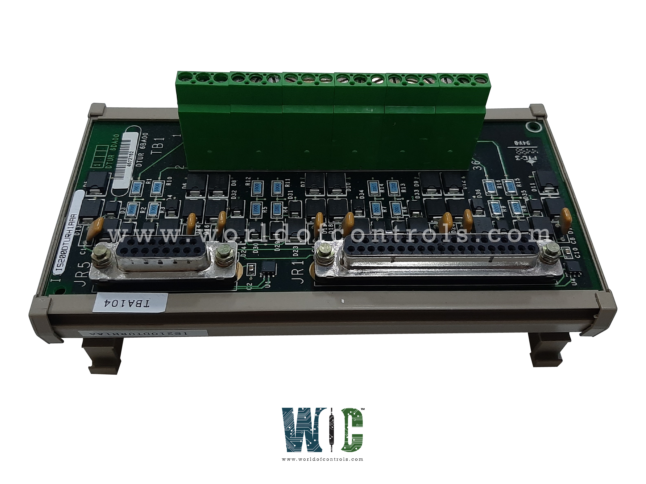
World Of Controls understands the criticality of your requirement and works towards reducing the lead time as much as possible.
IS200DTURH1AA - Pulse Rate Terminal Board is available in stock which ships the same day.
IS200DTURH1AA - Pulse Rate Terminal Board comes in UNUSED as well as REBUILT condition.
To avail our best deals for IS200DTURH1AA - Pulse Rate Terminal Board, contact us and we will get back to you within 24 hours.
Part No.: IS200DTURH1AA
Manufacturer: General Electric
Country of Manufacture: United States of America (USA)
Size: 10.16 cm wide x 33.02 cm high
Temperature: -30 to +65 oC
Product Type: Pulse Rate Terminal Board
Availability: In Stock
Series: Mark VI
IS200DTURH1AA is a pulse rate terminal board developed by GE. It is a part of Mark VI control system. The board serves as a compact solution for pulse-rate measurement, specifically designed for DIN-rail mounting. The DTUR board is designed for DIN-rail mounting in industrial environments. Its compact design allows for easy installation and integration into existing systems.
The WOC team is always available to help you with your Mark VI requirements. For more information, please contact WOC.
What is IS200DTURH1AA?
It is a pulse rate terminal board developed by GE under the Mark VI series.
What are the Terminal board connectors JR1 and JR5 used for?
Terminal board connectors JR1 and JR5 serve as interface points for connecting external devices or subsystems to the system. They play a crucial role in transmitting signals and data between the terminal board and connected components.
What is the purpose of the ID device on connectors JR1 and JR5?
The ID device on connectors JR1 and JR5 contains essential information such as the terminal board serial number, board type, revision number, and plug location. This information is crucial for system identification and configuration.
What happens if there is a mismatch encountered during ID chip interrogation?
When the ID chip on connectors JR1 and JR5 is interrogated by VTUR and a mismatch is encountered, a hardware incompatibility fault is created. This fault indicates potential issues with hardware configuration or compatibility, prompting further investigation and corrective action.
How does the ID chip aid in system maintenance and troubleshooting?
The ID chip provides vital information about the terminal board, enabling quick identification and configuration. In the event of a mismatch, it serves as an indicator of potential hardware compatibility issues, allowing for efficient troubleshooting and resolution.
Are there any specific procedures for addressing hardware incompatibility faults?
Yes, when a hardware incompatibility fault is detected, it is essential to review the hardware configuration and ensure that all components are compatible and properly connected. Resolving the fault may involve replacing incompatible hardware or updating firmware to ensure compatibility.