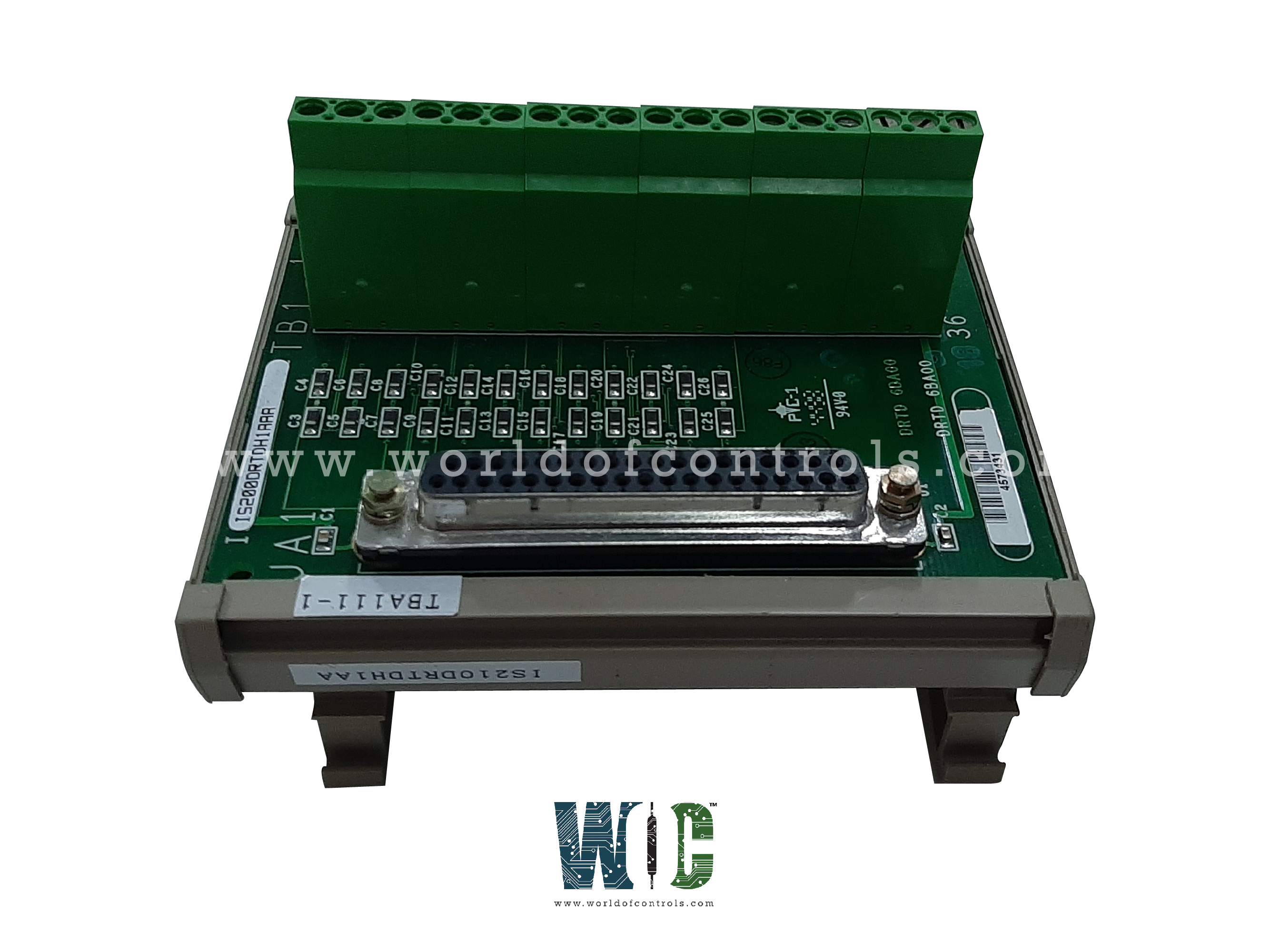
IS200DSCBH1ABB - Serial Input/Output Board

IS200DSCBH1ABB - Serial Input/Output Board IS200DSCBH1ABB - Serial Input/Output Board

World Of Controls understands the criticality of your requirement and works towards reducing the lead time as much as possible.

IS200DSCBH1ABB - Serial Input/Output Board is available in stock which ships the same day.

IS200DSCBH1ABB - Serial Input/Output Board comes in UNUSED as well as REBUILT condition.

To avail our best deals for IS200DSCBH1ABB - Serial Input/Output Board, contact us and we will get back to you within 24 hours.

SPECIFICATIONS

Part No.: IS200DSCBH1ABB
Manufacturer: General Electric
Country of Manufacture: United States of America (USA)
Number of Channels: 6
Temperature: -30 to 65oC
Size: 8.6 cm Wide X 16.2 cm High
Product Type: Serial Input/Output Board
Availability: In Stock
Series: Mark VI

Functional Description

IS200DSCBH1ABB is a Serial Input/Output Board developed by GE. It is a part of Mark VI control system. The DSCB stands as a compact and specifically designed interface terminal board engineered for DIN-rail mounting within the system architecture. Its primary function involves establishing connectivity with the Serial Communications Board (VSCA) through a 37-wire cable. The VSCA serves as a crucial component providing communication interfaces to external devices, utilizing RS-232C, RS422, and RS485 serial communication protocols. The board, through its robust physical construction, intelligent connectivity capabilities, and noise-suppressed signal transmission, plays a crucial role in ensuring seamless communication and interaction between the VSCA and a diverse array of external devices critical to the system's functionality.

Features

  • Communication Interfaces and Connected Devices: The board acts as the intermediary link between VSCA and various external devices. These external devices encompass a range of intelligent pressure sensors, notably including sophisticated sensors like the HoneywellTM Pressure Transducers. Additionally, it connects with and facilitates communication for KollmorgenTM Electric Drives utilized in valve actuation processes.
  • Mounting and Physical Configuration: Mounted within a plastic frame, the board is structured for vertical DIN-rail mounting, ensuring a secure and space-efficient placement within the system. The board incorporates high-density Euro-Block type terminal blocks, permanently affixed, featuring dual screw connections specifically designated for the ground connection (SCOM).
  • Wiring and Signal Transmission: Wiring connections to the external devices are established using shielded twisted pairs, optimizing signal integrity and minimizing interference. Moreover, the DSCB incorporates on-board noise suppression mechanisms to ensure clean and reliable communication signals across the connected devices.
  • Identification and Diagnostic Integration: For system diagnostic purposes and seamless integration within the architecture, the module includes an on-board identification (ID) chip. This chip plays a vital role in identifying and authenticating the board to the VSCA, facilitating diagnostic procedures, and system monitoring for optimal performance and maintenance.

Installation

  • Ground (SCOM) Connection: The Euro-Block type terminal block accommodates four terminals dedicated to the SCOM (ground) connection. It's crucial to ensure these connections are kept as short as possible, optimizing grounding effectiveness within the system.
  • Configuration Jumpers (J1 - J6) for SIGRET and Shield Grounding: Jumpers J1 - J6: These jumpers serve the purpose of directing SIGRET, a signal return line, either directly to SCOM or via a capacitor connected to SCOM.
  • Shield Grounding Configuration: The shield, which is part of the cable's shielding mechanism, should be grounded at one end, either at the device end or the terminal block end, but not both simultaneously.
  • Shield Grounding Guidelines: If the shield is grounded at the device end, it's recommended to configure the jumpers to include the capacitor in the circuit. This setup ensures effective suppression of noise and interference, contributing to improved signal quality and reliability.
  • Shield Not Grounded at Device End: Conversely, if the shield remains ungrounded at the device end, the jumper settings should be adjusted to direct SIGRET directly to SCOM without routing through the capacitor. This configuration prevents potential ground loops and ensures appropriate signal integrity.

The WOC team is always available to help you with your Mark VI requirements. For more information, please contact WOC.

Frequently Asked Questions

What is IS200DSCBH1ABB?
It is a Serial Input/Output Board developed by GE under the Mark VI series.

What is the purpose of the ID device on the terminal board and I/O board?
Both the board and the connected I/O board are equipped with their own unique ID device. This device serves the purpose of identification and compatibility verification within the system.

How does the ID device's information get utilized within the system?
During system operation, the I/O board interrogates and reads the information stored in the ID device of the connected terminal board. This data retrieval process is performed for compatibility checks and system validation.

What happens in case of a mismatch or discrepancy in the ID chip information?
If, during the reading process, the I/O board encounters a discrepancy or mismatch between the retrieved information and the expected specifications, a hardware incompatibility fault is triggered. This fault indicates that there's a potential issue or inconsistency in the identification or compatibility of the connected terminal board and I/O board.