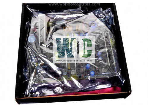
SPECIFICATIONS
Part No.: IS200DPWAG1A
Manufacturer: General Electric
Country of Manufacture: United States of America (USA)
Number of Channels:3
Input voltage: 28 V dc
Input current: Limited by protection to no more than 1.6 A steady state
Output voltage: 12 V dc
Product Type: Transducer Power Distribution Terminal Board
Availability: In Stock
Series: Drive Control
Functional Description
IS200DPWAG1A is a transducer power distribution terminal board developed by GE. It is a part of Drive Control system. The Transducer Power Distribution (DPWA) terminal board serves as a component in power distribution systems, offering a reliable and efficient solution for managing power supply to various external devices.
Mounting and Form Factor
- The terminal board is designed for DIN-rail mounting, ensuring easy and secure installation within control systems or industrial environments.
- Its compact form factor makes it suitable for space-constrained applications, optimizing utilization of available mounting space.
Input Voltage and Redundancy
- The board accepts an input voltage of 28 V dc 5 percent, which is supplied through a two-pin Mate-N-Lok connector.
- To enhance reliability and ensure uninterrupted operation, connectors are provided for two independent power sources, allowing the utilization of redundant supplies.
- The input is capable of accepting power from a floating isolated voltage source, offering flexibility in power source selection.
Voltage Centering and Attenuation
- The input to the board includes two 1 kohm resistors from positive and negative input power to SCOM, centering a floating power source on SCOM.
- Attenuated input voltage is provided for external monitoring, enabling efficient monitoring and management of input power levels.
Output Power and Connectivity
- The terminal board delivers output power of 12 V dc 5 percent to external devices through a Euro-type terminal block.
- Connectivity is facilitated through screw terminals and AWG 18 twisted-pair wiring, ensuring secure and reliable connections even in demanding industrial environments.
- The board provides three output terminal pairs, with a total output rated at 0 to 1.2 A, catering to diverse power distribution requirements.
Compatibility and Protection
- The outputs of the terminal board are compatible with the XDSAG AC interface board, offering seamless integration into existing systems.
- To safeguard connected devices and ensure system integrity, outputs are equipped with short circuit protection mechanisms and are self-recovering, minimizing downtime and enhancing operational reliability.
Installation
- Mounting on DIN-Rail: Begin by mounting the DPWA assembly securely on a standard DIN-rail. Ensure that the DIN-rail provides a stable and reliable mounting platform for the board.
- Connecting Input Power: Connect the input power source to connector P1 on the DPWA terminal board. This connector serves as the primary input point for supplying power to the board. In cases where multiple DPWA boards are utilized within the system, utilize connector P2 as a pass-through connection point for the power to additional boards. This ensures efficient distribution of power across multiple boards.
- Redundant Power Input (Optional): If a redundant power input is available for added reliability, connect the redundant power source to connector P3 on the DPWA terminal board. Utilize connector P4 as the pass-through connection point to distribute redundant power to additional DPWA boards, if applicable.
- Connecting Output Power Circuits: Identify and connect the wires for the three output power circuits to the designated screw terminal pairs on the DPWA terminal board. Utilize screw terminal pairs 9-10, 11-12, and 13-14 for connecting the output power circuits. Ensure secure and proper connections to minimize the risk of loose connections or electrical faults.
The WOC team is always available to help you with your Drive Control requirements. For more information, please contact WOC.
Frequently Asked Questions
What is IS200DPWAG1A?
It is a transducer power distribution terminal board developed by GE under the Drive Control series.
What monitoring capabilities does the board offer for input power?
The board features three voltage outputs specifically designed for monitoring input power. These outputs are attenuated to permit accurate readings of the 28 V dc input power using a 5 V dc full-scale input.
What are the specific voltage monitor outputs provided by the DPWA board?
Terminal 1 (PSRet)- Attenuated voltage present on the power input return line. Terminal 3 (PS28VA)- Attenuated voltage present on the P1 positive power input line. Terminal 5 (PS28VB)- Attenuated voltage present on the P3 positive power input line.
How do the terminals 2, 4, and 6 function in relation to the attenuator signals?
Terminals 2, 4, and 6 serve as a return SCOM path for the attenuator signals, ensuring proper signal flow and functionality within the system.
What is the significance of monitoring PS28VA and PS28VB in redundant systems?
In redundant systems, monitoring PS28VA and PS28VB enables the detection of a failed or missing redundant input, ensuring continuous and reliable power supply operation.
