SPECIFICATIONS
Part No.: IS200CPFXG1A
Manufacturer: General Electric
Function: Phase leg flash protection board
Series: Drive Control
Manual GEI-100414
No.of Plug Connectors: 2, J1, and J2
No.of CPFX Boards Per Phase Leg: 1
Product Type: PCB
Assembly Level Base Level
Availability: In Stock
Country of Manufacture: United States (USA)
Functional Description
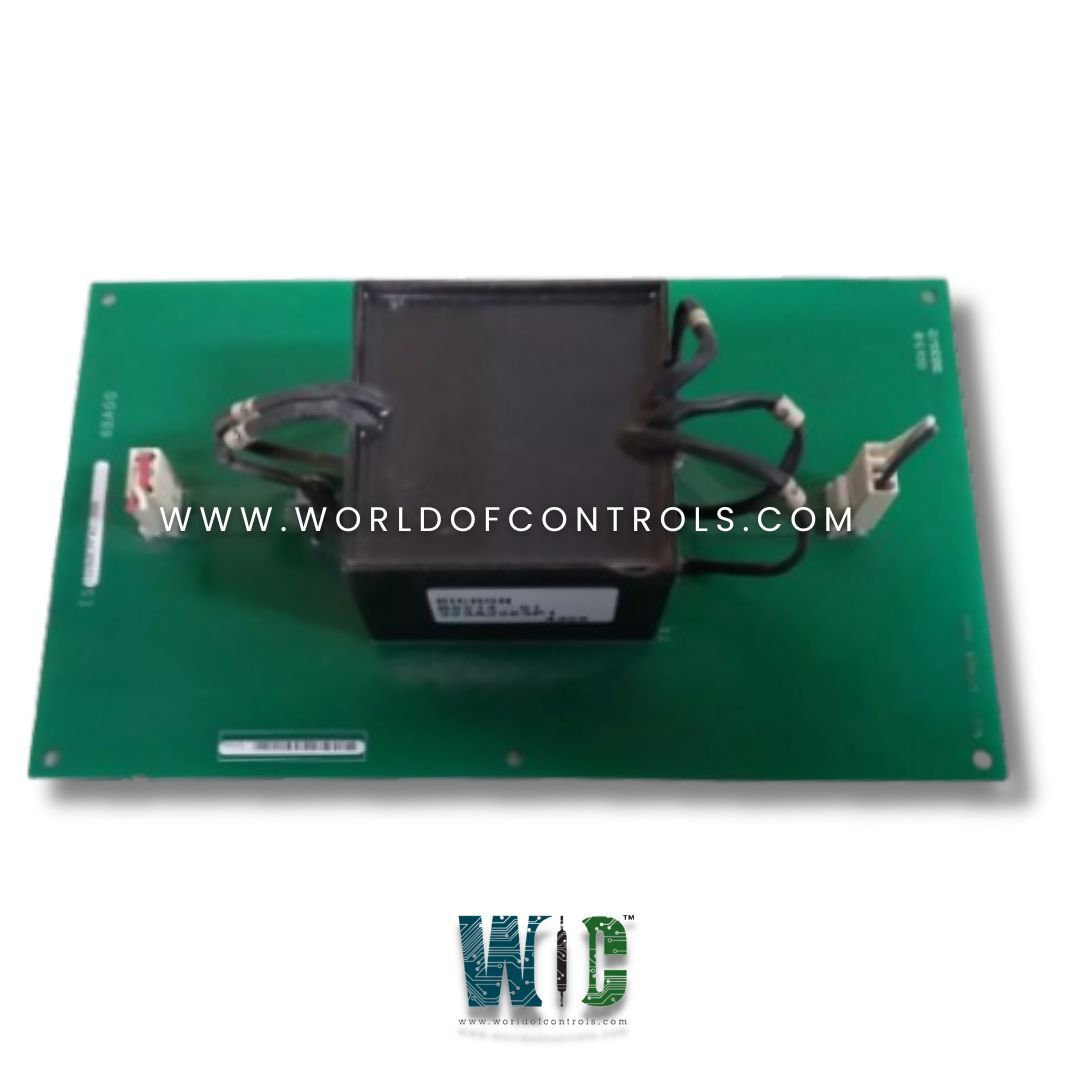
IS200CPFXG1A is a phase-leg flash protection board designed and developed by GE. It is developed under Drive Control series. The board's primary function is to isolate the power supply associated with the Phase Interface and Control Board (PICH). When used in conjunction with the PICH board, the CPFX board isolates power from a single phase leg from the other phase legs. This model is also suitable for simplex, dual, and triple redundant applications.
Features
- In Innovation Series drives, the board isolates the power supply for the PICH phase interface and control board or PICH.
- The board separates the power of one phase leg from the power of the other phase legs. This circuit board includes an isolation transformer labeled T1, as well as two connectors labeled J2 and J1. Each phase leg receives one CPFX board, and each bridge receives one CPFP control power flash protection card. The CPFP board is connected to each CPFX board via separate outputs.
- There are no fuses, LED indicators, test points, or user-adjustable hardware on the CPFX.
- It has two plug connectors that are labeled J2 and J1. The large and square-shaped transformer is centered on the surface of CPFX. A small electronic component labeled DS1 has been placed on the right next to the transformer.
System TMR Operation
- Voting systems are integral components of various computational processes, where input data needs to be collectively evaluated to produce reliable results. These systems employ a structured sequence of operations to ensure accuracy and consistency. The series of steps involved in each iteration of this process are input, vote, calculate, and output. The temporal framework in which these actions take place is referred to as a "frame." By allocating a fixed duration to these operations within a frame, the control program operates at a consistent and predictable pace, enhancing efficiency.
- In the context of SIFT (Single-Input Fault Tolerance) systems, a substantial portion of the fault-tolerant mechanisms is implemented through software. This approach is advantageous due to the inherent stability of software over time. Unlike hardware components, software tends to exhibit minimal degradation, thus ensuring the system's reliability over extended periods. The core concept of the SIFT design revolves around the utilization of just three identical controllers, which are seamlessly interconnected to facilitate the exchange of data among them.
- The key strength of the SIFT architecture lies in its software-centric approach. Practically all aspects of the system's operation, including data exchange, voting, and output selection, are efficiently managed by software components. This software-driven control empowers the system to adapt and evolve without undergoing hardware modifications, making it highly flexible and maintainable.
- However, there exists a specific scenario where the reliance on software is supplemented by hardware modifications. This pertains to the hardware output circuitry, where modifications are made to enable hardware-based voting. This exception highlights the strategic integration of hardware and software elements in achieving the system's overall objectives. Through this combined approach, the SIFT design achieves fault tolerance, stability, and adaptability while minimizing the need for continuous hardware enhancements.
World of Controls has the most comprehensive inventory of GE Speedtronic control parts. Our professionals are always ready to provide you with your GE OEM needs. If you require any additional information, please contact WOC immediately.
Frequently Asked Questions
What is IS200CPFXG1A?
It is a phase leg flash protection board designed and developed by GE.
How many plug connectors does the board have, and what are they labeled as?
The product has two plug connectors labeled J1 and J2.
How many CPFX boards are required per phase leg?
One CPFX board is required per phase leg.
What is the assembly level of the board?
The assembly level of the product is Base Level.
Are there any fuses, LED indicators, test points, or user-adjustable hardware on the module?
No, there are no fuses, LED indicators, test points, or user-adjustable hardware on the board.
Is the product suitable for simplex, dual, and triple redundant applications?
Yes, the product is suitable for simplex, dual, and triple redundant applications.
