SPECIFICATIONS
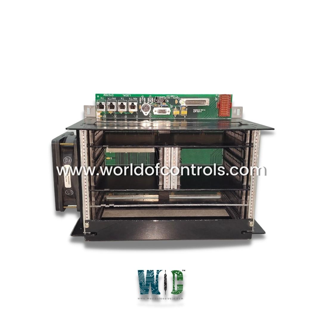
Part No.: IS200CABPG1BAA
Manufacturer: General Electric
Country of Manufacture: United States of America (USA)
Temperature: -30 to 65oC
Technology: Surface-mount
Product Type: Control Assembly Backplane
Availability: In Stock
Series: Drive Control
Functional Description
IS200CABPG1BAA is a control assembly backplane developed by GE. It is a part of the drive control series. The Control Assembly Backplane (CABP) board represents a pivotal component within the intricate architecture of the Innovation Series drive system. As a multi-layer printed wiring board, its primary function revolves around facilitating the seamless interconnections necessary for the various printed wiring boards inserted into it, while also serving as a conduit for crucial external signal interfaces.
Supported Boards
- Bridge Interface Board (BAIA): This board facilitates essential bridge interface functionalities crucial for the system's operation.
- Auxiliary Genius Interface Module (GBIA), Auxiliary Profibus Interface Module (PBIA), or Application Control Layer Board (ACL_): These boards augment the system's capabilities in auxiliary control and interface tasks, catering to various operational demands.
- Digital Signal Process Control Board (DSPX) (Optional): This optional board provides advanced digital signal processing capabilities, enhancing the system's functionality.
- Rack Power Supply Board (RAPA): Integral for managing power distribution within the system, ensuring efficient and reliable power delivery.
- Bridge Interface Board (BIC_): Another variant of the bridge interface board, offering flexibility in system configuration.
- Drive Bridge Personality Interface Board (BPI_) or Bridge Interface Board (FOSA): These boards facilitate seamless interaction between the drive and its associated bridge personalities, optimizing performance.
External Interface Connectors
- User Control Inputs/Outputs (I/O): Enabling user interaction and control over the drive system's functionalities.
- Front Panel Meters: Providing real-time monitoring of key system parameters for enhanced operational visibility.
- Diagnostic/Configuration Tools: Essential for diagnosing issues and configuring the drive system to meet specific operational requirements.
- Front Panel Keypad: Facilitating user-friendly input and control access directly from the drive system's front panel.
- ISBus Ports: Enabling communication with other ISBus-compatible devices, fostering interoperability within broader control systems.
- Power Supply Inputs: Ensuring reliable power input to sustain the system's operation under varying conditions.
Mounting and Integration
- Securely mounted onto the Innovation Series board rack, leveraging its designated mounting points.
- This integration within the rack structure not only ensures the secure housing of individual boards but also reinforces the structural integrity of the overall system, contributing to its robust and reliable performance across diverse operational scenarios.
Hardware Features
- Terminal Board Placement: The terminal boards associated with the board for user Input/Output (I/O) functionalities are strategically positioned near the entry point of application cables into the cabinet. This placement ensures convenient access and efficient connectivity within the system setup.
- Cable Connection: Connection to these terminal boards is facilitated through two distinct multi-conductor cables, meticulously segregated to cater to differing voltage requirements. One cable is dedicated to low-voltage applications (less than 50 volts), while the other is designated for high-voltage applications (greater than 50 volts). This meticulous separation mitigates potential risks and ensures safe operation within specified voltage parameters.
- Connector Design: The design of the board incorporates meticulous measures to prevent erroneous connections and safeguard against operational mishaps. Non-board connectors are ingeniously engineered to be incapable of incorrect insertion, employing a variety of methods
- Diverse Connector Types: Different connector types are utilized for each distinct function, ensuring compatibility while preventing misconnections.
- Unique Keying Mechanisms: Each connector is uniquely keyed, thereby eliminating the possibility of incorrect insertion by ensuring that connectors only fit into their designated sockets.
- Spatial Separation: Similar connectors are spaced apart with ample separation, rendering incorrect insertion physically impossible. This spatial arrangement enhances operational safety and reduces the likelihood of inadvertent errors.
- Connector Integrity: The connectors employed on the board uphold stringent standards of integrity and compatibility, further enhancing the reliability and robustness of the system. These connectors adhere to one of the following principles
- Individual Keying: Each connector is individually keyed to its corresponding socket, guaranteeing precise alignment and secure attachment.
- Diverse Connector Sizes: Similar modules utilize different connector sizes, such as 96-pin versus 128-pin variants, ensuring clear differentiation and preventing interchangeability issues.
- Common Pin Assignments: Modules feature common pin assignments across compatible connectors, facilitating seamless interchangeability without risk of damage or operational impairment.
The WOC team is always available to help you with your drive control requirements. For more information, please contact WOC.
Frequently Asked Questions
What is IS200CABPG1BAA?
It is a control assembly backplane developed by GE under the Drive Control series.
What are User Control Inputs/Outputs (I/O)?
User Control Inputs/Outputs (I/O) facilitate user interaction and control capabilities within the drive system. These connectors empower users to manipulate and oversee various aspects of system operation, enhancing flexibility and responsiveness to operational demands.
What is the Purpose of Front Panel Meters?
Front Panel Meters provide real-time monitoring of critical system parameters, offering users immediate visibility into the system's performance. By presenting key metrics in real-time, these meters enable operators to make informed decisions and maintain optimal system operation.
Why are Diagnostic/Configuration Tools Important?
Diagnostic/Configuration Tools are indispensable for identifying and resolving system issues, as well as tailoring system configurations to meet specific operational requirements. These tools play a vital role in ensuring the system operates at peak efficiency and reliability.
