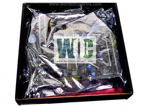
SPECIFICATIONS
Part No.: IS200BPDIH1A
Manufacturer: General Electric
Country of Manufacture: United States of America (USA)
Temperature: -30 to 65oC
Size: 10.16 cm wide x 33.02 cm high
Number of channels: 12
Input span, transmitters: 1-5 V dc from 4-20 mA input
Outputs: 24 V outputs provide 21 mA each
Product Type: Discrete Input Module
Availability: In Stock
Series: Drive Control
Functional Description
IS200BPDIH1A is a Discrete Input Module developed by GE. It is part of Drive Control series. The Discrete Input pack serves as the electrical interface connecting I/O Ethernet networks to a discrete input terminal board. It includes a processor board shared across all Mark*VIe distributed I/O packs, alongside an acquisition board dedicated to handling discrete input functions.
Processor features
- High-Speed Processor with Memory: At its core, the Processor incorporates a high-speed processor supported by ample RAM and flash memory. This configuration ensures rapid data processing and efficient handling of inputs and outputs across the network.
- Ethernet Connectivity: The Processor includes two fully independent 10/100 Ethernet ports, each equipped with dedicated connectors. These ports enable seamless integration into one or two I/O Ethernet networks, facilitating reliable data communication and network redundancy.
- Watchdog Timer and Reset Circuit: To enhance reliability, the Processor is equipped with a hardware watchdog timer and reset circuit. These components monitor system operation and automatically reset the Processor in the event of a fault or lock-up, ensuring continuous operation and minimal downtime.
- Internal Temperature Sensor: An integrated internal temperature sensor provides real-time monitoring of the Processor's operating temperature. This feature helps maintain optimal performance and prevents overheating by triggering alerts or adjustments to cooling systems as needed.
- Status-Indication LEDs: The Processor is equipped with status-indication LEDs that provide visual feedback on its operational state. These LEDs inform users of power status, network connectivity, and system health, aiding in troubleshooting and maintenance.
- Electronic ID Functionality: The Processor includes electronic ID capabilities, enabling it to possess a unique identifier. It can also read IDs from other boards within the system. This feature supports efficient configuration management and troubleshooting by identifying specific components within the network.
- Power Management Features: The Processor integrates an input power connector with soft start and current limiting capabilities. This design feature ensures smooth power-up sequences, reducing inrush currents and enhancing system reliability during startup. Additionally, local power supplies with sequencing and monitoring capabilities are included to further stabilize voltage levels and ensure consistent operation.
Safety Precautions for Handling and Maintenance
Ensuring safety protocols during the handling and maintenance of electrical boards is crucial to prevent accidents, equipment damage, and static-related issues. Here are essential safety guidelines to adhere to:
- Power Shutdown and Verification: Before handling the board or any connected circuits, turn off the power supply to the board. Perform a thorough test to confirm the absence of power on the board. Always verify the absence of electrical power to avoid potential electric shock hazards before any contact.
- Refrain from removing or re-inserting boards or connections while power is actively applied to the drive. Doing so could lead to equipment damage or malfunction.
- Consider all boards as static-sensitive components. When replacing or handling boards, employ a grounding strap. This strap helps dissipate static electricity, safeguarding the board from potential damage due to electrostatic discharge.
- When not in use, store boards in anti-static bags or boxes they were originally shipped in. This practice prevents the buildup and discharge of static electricity, mitigating the risk of damage to sensitive electronic components.
- Careful Handling of Mounting Hardware: Be cautious to avoid dropping any mounting hardware into the unit. Dropping hardware can potentially cause damage to internal components or disrupt the functionality of the equipment.
- Adhering to these safety measures significantly reduces the risk of electric shock, equipment damage, and static-related issues while handling, replacing, or maintaining electrical boards, ensuring a secure and efficient working environment for maintenance procedures.
Voltage Compatibility
- In 240 V AC applications, it's critical to avoid inadvertently cross-connecting the 240 V AC and DC voltages. Doing so can lead to a failure due to the peak voltage exceeding the Metal Oxide Varistor (MOV) rating. The failure occurs because most AC supplies operate with a grounded neutral. If an accidental connection between the 125 V DC and the AC voltage is established, the sum of the AC peak voltage and the 125 V DC is applied to the MOVs connected between DC and ground.
- However, in 120 V AC applications, the MOV rating can withstand the peak voltage without causing a failure. This difference in voltage levels between 120 V AC and 240 V AC is crucial to consider when designing and configuring electrical systems to prevent damage to components and ensure proper functionality. It highlights the importance of careful wiring and adherence to voltage compatibility guidelines to maintain system integrity and safety.
The WOC team is always available to help you with your Drive Control requirements. For more information, please contact WOC.
Frequently Asked Questions
What is IS200BPDIH1A?
It is a Discrete Input Module developed by GE under the Drive Control series.
What precautions should be taken to prevent equipment damage?
Avoid removing, re-inserting, or making connections while power is applied to the drive, as this can cause equipment damage. It's crucial to perform such tasks only when power is turned off.
How should I handle boards in terms of static sensitivity?
Treat all boards as sensitive to static electricity. Utilize a grounding strap when changing boards to dissipate static charge. Additionally, store boards in anti-static bags or the original shipping boxes to minimize static-related risks.
