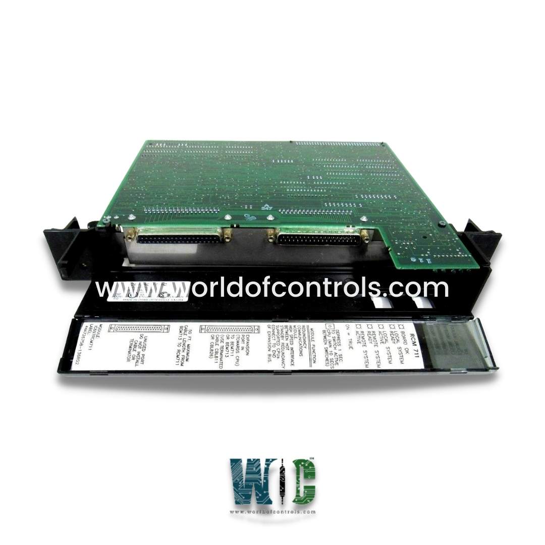
IC697RCM711 - Redundancy Communications Module

IC697RCM711 - Redundancy Communications Module IC697RCM711 - Redundancy Communications Module

World Of Controls understands the criticality of your requirement and works towards reducing the lead time as much as possible.

IC697RCM711 - Redundancy Communications Module is available in stock which ships the same day.

IC697RCM711 - Redundancy Communications Module comes in UNUSED as well as REBUILT condition.

To avail our best deals for IC697RCM711 - Redundancy Communications Module, contact us and we will get back to you within 24 hours.

SPECIFICATIONS

Part No.: IC697RCM711
Manufacturer: General Electric
Product Type: Redundancy Communications Module
Availability: In Stock
Number of Slots: One (Single Slot)
Number of LEDs: 5
Connects to: MS-DOS
Serial Ports: 2 (1 not used)
Current Required: 0.7 amps
Series: VersaMax

Functional Description

IC697RCM711 is a redundant communications module developed by GE Fanuc. The Redundant Communications Module is a component in GE Fanuc's redundancy systems, ensuring smooth operation, synchronization, and data transfer between primary and secondary PLCs. Its robust design and support for Hot Standby and Enhanced Hot Standby configurations make it an ideal solution for applications requiring high availability and minimal downtime.

Features

  • High-Speed Parallel Bus Expansion Interface: This module facilitates high-speed communication between the Primary and Secondary PLCs in a redundant system. This communication ensures seamless synchronization and data exchange.
  • Supports Hot Standby and Enhanced Hot Standby: Hot Standby and Enhanced Hot Standby configurations allow for real-time failover from the active (primary) CPU to the backup (secondary) CPU. This ensures minimal downtime in case of a system failure.
  • CPU Redundancy System Configurations: It supports various CPU redundancy systems, allowing critical processes to continue uninterrupted by switching control from the active CPU to a backup one.
  • Shared I/O and Synchronizing Message: Provides a pathway for transferring shared I/O data and synchronizing messages between the primary and secondary units, ensuring both units remain in sync.
  • Manual Switch for Control: A pushbutton switch allows the manual transfer of control from the active unit to the backup unit, enabling maintenance on the active unit while the system remains online.
  • Software Configuration: The module is configured using MS-DOS programming software, allowing customization of the redundancy setup.

LED Indicators

LED Indicators offer a quick visual reference for the status of the module and system:

  • BOARD OK: Indicates that the board is functioning properly.
  • LOCAL READY/ACTIVE: Shows the status of the local system.
  • REMOTE READY/ACTIVE: Shows the status of the remote system connected via the expansion bus.

Board Functions

  • The RCM creates a path for synchronizing messages between the active and backup units in Hot Standby and Enhanced Hot Standby configurations. This synchronization ensures that both CPUs are aware of the system’s current state and can take over if necessary.
  • The module enables the transfer of shared I/O data between the two units, ensuring that both primary and backup units have the same real-time data.
  • The module can support up to 25 feet (7.5 meters) of interconnecting cable between redundant units, providing flexibility in system configuration.
  • It is compatible with IC697CPU780, IC697CGR935, and IC697CGR772 CPUs in Hot Standby configurations.

Installation

  • Power Off: Ensure that the rack power is turned off before installation.
  • Slot Position: The RCM should be installed in any slot of rack 0, except for slot 1.
  • Cabling: Connect the module using appropriate cables, either IC697CBL811 or IC697CBL826, depending on the required length.
  • Ensure Rack Power is Off: Before handling any components, make sure that the system is powered down to avoid damage or improper installation.
  • Install in Rack 0: Insert the RCM into any available slot in rack 0 (except slot 1, which is reserved for other uses).
  • Connect the Cables: Use either the IC697CBL811 (10 feet/3 meters) or IC697CBL826 (25 feet/7.5 meters) cable to connect the module to the redundant system.
  • Power On the System: Once the module is installed and wired, turn the rack power back on to begin system operation.

I/O Bus Termination

The I/O bus termination is integral to ensuring the reliability and ease of maintenance within a control system. To facilitate the simple and efficient replacement of a faulty Redundant Control Module (RCM), it is crucial that the RCM is strategically positioned at the end of the expansion bus. This specific location not only simplifies the replacement process but also minimizes any potential disruption to the expansion bus during necessary system maintenance. The RCM connects to the bus via a specialized terminated cable, either the IC697CBL811 or IC697CBL826. This dedicated connection enhances stability and reduces the likelihood of signal interference, ensuring consistent operational performance during both normal and maintenance activities.

Expansion Rack Attachment

When there is a need for increased system capacity or additional functionalities, the system can accommodate this by adding expansion racks. The integration of these additional racks involves a Bus Transmitter Module (BTM) located in the CPU rack, which connects to a Bus Receiver Module (BRM) situated in the expansion rack. This connection is facilitated using the IC600WDXXX cable, with "XXX" designating the length of the cable in feet. The modular design allows for the daisy-chaining of additional racks, which expands the system's capabilities while keeping the RCM as the last component in the chain. This arrangement is advantageous because it helps maintain the integrity and efficiency of data transmission across the bus while enabling flexible system expansion tailored to specific operational needs.

Maintenance and Manual Control

Maintenance and manual control functionalities are critical components of the RCM design. In scenarios where maintenance is required on the active CPU, the RCM is equipped with a pushbutton switch that enables operators to manually switch to the backup unit. This design feature allows for maintenance activities to occur without taking the entire system offline, thereby ensuring continuous operation throughout the servicing process. The ability to switch to the backup unit seamlessly is crucial in environments where uptime is essential, as it prevents disruption to operations and maintains system availability.

Core Functionality and Redundancy Communication

The core functionality of the RCM centers around its role in enabling redundancy communication between the active and backup units. It establishes a dedicated pathway for the synchronization of messages, which is essential for ensuring that both units operate in alignment. This synchronization process guarantees that the backup unit is fully prepared to take over if the active unit experiences a failure. Such redundancy is not just a safety feature; it is a fundamental aspect of maintaining continuous operation and minimizing downtime in critical systems. By ensuring that both units are constantly aligned and ready for immediate switchover, the RCM enhances the overall reliability and resilience of the control system, ultimately contributing to operational efficiency and stability in demanding environments.

Board Removal  Procedure

  • To remove a module from the rack, begin by ensuring you have a firm grip on the board itself. Place your thumbs on the front of the board cover, positioning them at the top, while your fingers should wrap around the back, making contact with the plastic clips that secure the cover in place. This grip provides stability and control as you proceed with the removal process.
  • Next, focus on the rack clips located at the back of the cover. With your fingers, gently squeeze these clips to disengage them from the rack rail. It is essential to apply sufficient pressure to ensure that the clips release their grip without causing any undue stress or damage to the board or the surrounding components. As you perform this action, maintain a steady hold on the board to prevent it from slipping or falling.
  • Once the clips are disengaged, you can proceed to pull the board firmly away from the backplane connector. This step requires a deliberate motion to ensure a clean separation from the connector, which can often be snug due to the precision fitting of the components. As you pull the board, make sure to keep it aligned with the card guide to avoid any potential interference with adjacent modules.
  • After successfully disconnecting the board from the backplane, slide it along the card guide to facilitate its removal from the rack. This sliding motion is crucial for a smooth extraction, as it allows the board to clear any obstructions and ensures that the connectors remain undamaged. Continue this motion until the board is completely free from the rack, at which point you can safely set it aside for maintenance, replacement, or inspection. Following these steps will help ensure a safe and effective removal process while maintaining the integrity of both the module and the overall system.

The WOC team is always available to help you with your Mark I and II requirements. For more information, please contact WOC.

Frequently Asked Questions

What is IC697RCM711?
It is a Redundancy Communications Module developed by GE under VersaMax series.

How does the module support redundancy communication?
The module facilitates redundancy communication by providing a path for synchronizing messages between the active and backup units. This ensures that the backup unit is fully synchronized and ready to take over in the event of a failure of the active unit.

How does it handle I/O data transfer?
The module manages the transfer of I/O data between the active and backup units, ensuring that both units have consistent and up-to-date data. This helps maintain uninterrupted system operations even during unit switches.

What is the difference between Hot Standby and Hot Standby CPU Redundancy?
Both configurations involve one CPU operating as the active controller while the other remains on standby. Hot Standby ensures that the backup unit is ready to take over if needed, enhancing system reliability and availability.