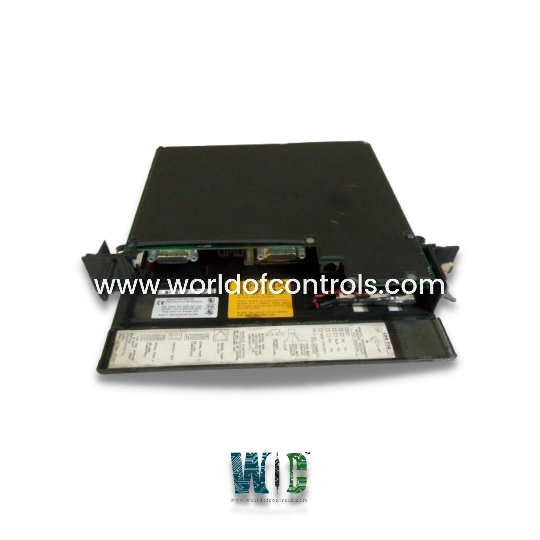
World Of Controls understands the criticality of your requirement and works towards reducing the lead time as much as possible.
IC697CPX772 - 32-Bit Point Single Slot CPU Module is available in stock which ships the same day.
IC697CPX772 - 32-Bit Point Single Slot CPU Module comes in UNUSED as well as REBUILT condition.
To avail our best deals for IC697CPX772 - 32-Bit Point Single Slot CPU Module, contact us and we will get back to you within 24 hours.
SPECIFICATIONS:
Part No: IC697CPX772
Manufacturer: General Electric Fanuc
Product Type: 32-Bit Point Single Slot CPU Module
Series Series 90-70
Nominal Rated Voltage: 120 VAC
Input Voltage Range: AC Input 90-132 VAC
Input Power: 160 watts
Product type: CPU module
RAM: 512 kilobytes
Processor: 80486DX4
NV-RAM: 256 kilobytes
Clock speed: 96 megahertz
Current draw: 3.1 Amps
Input Half Cycle Peak Inrush: 55 amps
Output Power: 100 watts
Voltage input: 5 Volts DC
Current required from 5V Bus: 1.2 A
Backplane Current draw: 1.2 Amperes
Maximum cable length: 15 m
Effective data rate: 500 Kbytes / sec
Size: 8.83 x 3.58 x 4.7 inches
Product Lifecycle: Discontinued By Manufacturer
Availability: In Stock
Country of Origin: USA
FUNCTIONAL DESCRIPTION:
IC697CPX772 is a 32-Bit Point Single Slot CPU Module manufactured and designed by General Electric as part of the Mark II Series used in GE Speedtronic Control Systems. The CPU module is powered by an 80486DX4 microprocessor running at 96 MHz, offering robust performance for industrial control applications. It features three independent serial ports, accessible from the front of the module, which can be used to connect serial devices or programming terminals. Port 1 utilizes the RS-232 protocol and comes with a 6-pin RJ-11 connector. Port 2 and Port 3 both support the RS-485 protocol, but with a key difference: Port 2 is optocoupler isolated, providing added protection, while Port 3 is not isolated. Port 2 uses a 15-pin female D-connector. The module operates on a 5V DC power supply and has a current consumption rating of 3.1 Amps. It is designed to function within a temperature range of 32°F to 140°F (0°C to 60°C), making it suitable for various industrial environments. For cooling, it supports three types of rack fan assemblies: 120V AC, 240V AC, and 24V DC-powered options.
The CPX772 is a single slot PLC CPU that is programmed and configured by MS-DOS or Windows-based programming software to perform real-time control of machines, processes and material handling systems. It communicates with I/O and smart option modules over the rack-mounted backplane using the VME C.1 Standard format. Supported option modules include LAN Interface modules, Programmable Coprocessor, Alphanumeric Display Coprocessor, Bus Controller for IC660/661 I/O products, Communications modules, I/O Link Interface, and all of the IC697 family of discrete and analog I/O modules.
INSTALLATION:
CONFIGURATION:
The IC697 CPU and I/O system is configured with MS-DOS or Windows-based programming software, although the MS-DOS software does not support all features, such as Bulk Memory Area (BMA), which requires the Windows software version 2.2 or later. See the IPI shipped with this module for programming software feature support details. There are no DIP switches or jumpers used to configure the system. The CPU verifies the actual module and rack configuration at power-up and periodically during operation. The actual configuration must be the same as the programmed configuration. Deviations are reported to the CPU alarm processor function for configured fault response. Refer to the applicable Programming Software User‘s Manual for a description of configuration functions.
WOC has the largest stock of OEM Replacement Parts for GE Speedtronic Gas Turbine Control Systems. We can also repair your faulty boards and supply unused and rebuilt boards backed up with a warranty. Our team of experts is available around the clock to support your OEM needs. Our team of experts at WOC is happy to assist you with any of your automation requirements. For pricing and availability on parts and repairs, kindly contact our team by phone or email.
Can it be programmed with standard PLC languages?
Yes, most modules of this type support programming using IEC 61131-3 standard languages, including Ladder Diagram (LD), Structured Text (ST), Function Block Diagram (FBD), Instruction List (IL), and Sequential Function Chart (SFC). This flexibility makes integration with existing control systems straightforward.
What communication protocols are supported?
These modules typically support a wide range of communication protocols, such as Modbus RTU/TCP, Ethernet/IP, Profibus, Profinet, CANopen, and RS-232/RS-485. This ensures compatibility with various industrial networks and allows for easy integration with other automation devices.
What is the difference between a single-slot and multi-slot CPU module?
A single-slot CPU module contains all necessary processing and communication components within one compact unit, making it ideal for space-constrained applications. In contrast, multi-slot configurations may use additional slots for extended memory, separate communication interfaces, or specialty modules, offering greater expansion but requiring more physical space.