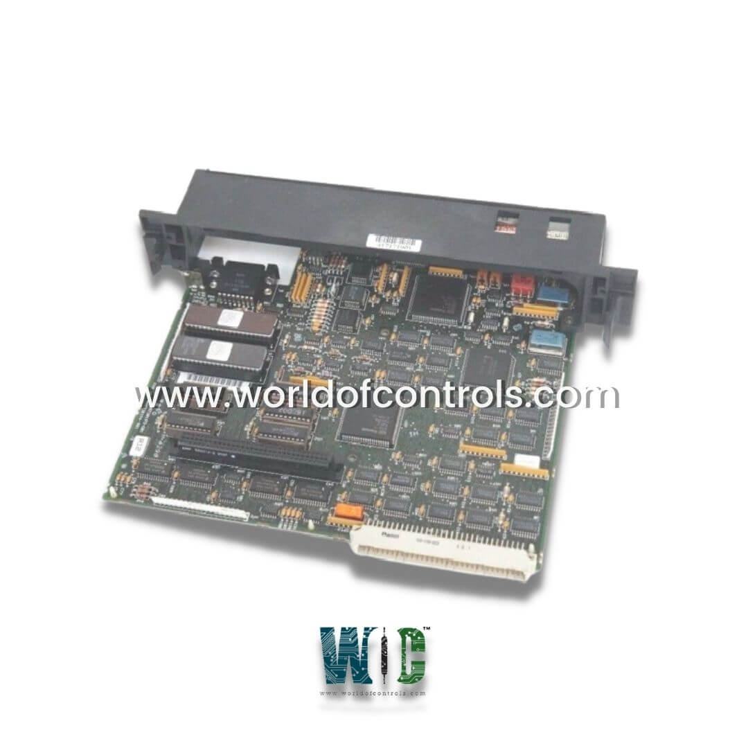
World Of Controls understands the criticality of your requirement and works towards reducing the lead time as much as possible.
IC697CPU771 - 12 MHz, Expandable CPU Module is available in stock which ships the same day.
IC697CPU771 - 12 MHz, Expandable CPU Module comes in UNUSED as well as REBUILT condition.
To avail our best deals for IC697CPU771 - 12 MHz, Expandable CPU Module, contact us and we will get back to you within 24 hours.
SPECIFICATIONS:
Part Number: IC697CPU771
Manufacturer: General Electric
Series: 90-70
Protocol Support: Genius
Isolation: 2000 volts Hi-Pot, 1500 volts
Bus Type: Daisy-chained bus cable
Bus Termination: 150 Ohm resistor
Communications: Global Data
Exchange rate: 128 bytes
LED Indicators: 2
Current Consumption: 300mA
Transient: 1500 Volts
Data Length: 128 bytes per message
Voltage: 5 Volts DC
Bus termination: 75/100/120/150 ohm resistor
Weight: 0.37 Kg
Shipping weight: 1.5 Kg
Country of Origin: United States
Availability: In Stock
Manual: GFK-0600F
FUNCTIONAL DESCRIPTION:
IC697CPU771 is a 12 MHz, Expandable CPU Module manufactured and designed by GE Mark 90-70 Series as part of the GE Speedtronic Gas Turbine Control Systems. The CPU 771 is a single slot PLC CPU, which is programmed and configured by MS-DOS or Windows-based programming software to perform real-time control of machines, processes, and material handling systems. The 771 CPU communicates with I/O and smart option modules over the rack-mounted backplane (IC697CHS750, 782, 783, 790, 791) by way of the VME C.1 Standard format. Supported option modules include all IC697 LAN interface modules, several Coprocessor modules, Bus Controller for IC660/661 I/O and Communications modules, in addition to all of the IC697 family of discrete and analog I/O modules. Program and data memory is available by the attachment of an expansion memory board with up to 512 Kbytes of battery-backed CMOS RAM.
INSTALLATION OF EXPANDABLE CPU MODULE:
It is the responsibility of the OEM, system integrator, or end user to install the PLC equipment for safe and reliable operation. Product manuals provide detailed information about installation, startup, and proper use of the PLC equipment. The installation manual, shipped with your PLC programming software, describes how to install the equipment. If the PLC installation must comply with supported standards, such as FCC or CE Directives, please refer to the Installation Requirements for Conformance to Standards, shipped with the PLC programming software, for additional guidelines.
The module should power up and blink the top LED. When the diagnostics have been completed successfully, the top LED stays on, and the middle and bottom LEDs are off. The CPU is now ready to be programmed. After the program has been verified, the toggle switch may be moved to the appropriate operation mode position. The LEDs indicate the position of the toggle switch and the state of the program.
CONFIGURATION:
The IC697 CPU and I/O system is configured with MS-DOS or Windows-based programming software. There are no DIP switches or jumpers used to configure the system. The CPU verifies the actual module and rack configuration at power-up and periodically during operation. The actual configuration must be the same as the programmed configuration. Deviations are reported to the CPU alarm processor function for configured fault response
WOC has the largest stock of OEM Replacement Parts for GE Speedtronic Turbine Control Systems. We can also repair your faulty boards and supply unused and rebuilt boards backed up with a warranty. Our team of experts is available around the clock to support your OEM needs. Our team of experts at WOC is happy to assist you with any of your automation requirements. For pricing and availability on parts and repairs, kindly contact our team by phone or email.
What is the Expandable CPU Module?
The Expandable CPU Module is a 12 MHz CPU Module manufactured by General Electric as part of the 90-70 Series. It is primarily designed for use in GE Speedtronic Gas Turbine Control Systems and serves as a PLC CPU in various industrial control systems.
What is the required voltage and power consumption for the CPU module?
The Expandable CPU Module operates on a 5 Volts DC power supply. It consumes a current of 300 mA during operation. Power requirements should be met to ensure stable functioning, and proper power management is necessary to avoid operational issues, especially when expanding the system.
How is the system configuration performed for the CPU module?
The CPU Module and its connected I/O system are configured using MS-DOS or Windows-based programming software. Unlike some older systems, there are no DIP switches or jumpers used for configuration. At power-up and periodically during operation, the CPU verifies the actual system configuration against the programmed configuration.