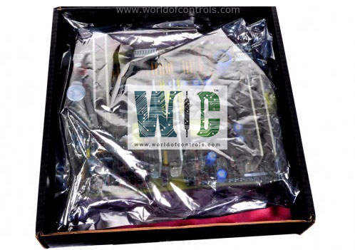
World Of Controls understands the criticality of your requirement and works towards reducing the lead time as much as possible.
IC697CGR935-JB - Single Slot CPU is available in stock which ships the same day.
IC697CGR935-JB - Single Slot CPU comes in UNUSED as well as REBUILT condition.
To avail our best deals for IC697CGR935-JB - Single Slot CPU, contact us and we will get back to you within 24 hours.
Part No: IC697CGR935-JB
Manufacturer: General Electric
Function: Single Slot CPU
Operating Temperature: 0 to 60 deg C (32 to 140 deg F)
Battery Shelf Life: 5 years at 20 deg C (68 deg F)
Inputs and Outputs: 12K each (any mix)
Serial Ports: 3
Current Required: 3.1 Amps nominal
Series: Mark I and II
Repair: 3-7 Day
Availability: In Stock
Country of Manufacturer: United States (USA)
IC697CGR935-JB is a Single Slot CPU developed by GE. It is a part of Mark I and II control system, specifically designed for CPU redundancy applications. This module is part of the redundant control system, where it plays a crucial role in managing fluctuating point calculations necessary for ensuring uninterrupted operation of complex systems.
The module is equipped with its own memory board, which is responsible for handling data and program memory. This built-in memory allows the module to function efficiently and independently in a redundancy setup, ensuring that critical data is available at all times for system operations. The program memory is included within the module, reducing the need for external memory sources, thus simplifying the overall system architecture.
The module can be operated remotely, making it convenient for use in automated and large-scale industrial environments. Alternatively, it can also be controlled via the three-position RUN/STOP switch located on the module. This manual control option provides users with an easy way to toggle between different operational states.
The front of the module is equipped with LED indicators, which display the status of the CPU. These LEDs offer clear feedback, allowing operators to quickly assess the module's operational state and troubleshoot potential issues.
The installation of the module should be carried out following the instructions in the Programmable Controller Installation and Hot Standby CPU Redundancy Manual. This manual contains detailed guidance on proper module installation and configuration, ensuring optimal performance and system reliability. Here’s a step-by-step outline for installation:
Once the module has passed its diagnostic checks and the LEDs indicate normal operation, the system is ready for programming. The CPU can be programmed regardless of the position of the key switch, providing flexibility in program development and modification. After programming the CPU, the toggle switch can be set to the appropriate operational mode for the system's intended use. The system can be easily switched between run and stop modes, offering versatility and control in various operational scenarios.
WOC is happy to assist you with any of your GE requirements. Please contact us by phone or email for pricing and availability on any parts and repairs.
What is IC697CGR935-JB?
It is a Single Slot CPU developed by GE.
Can the module be operated remotely?
Yes, the module can be operated remotely. It also includes a three-position RUN/STOP switch for manual operation if preferred. This allows for greater control, whether in automated systems or manual configurations.
What kind of memory does the module have?
The module comes with a memory board, which handles both data and program memory. This enables the module to operate independently, ensuring critical data and program instructions are always available for the redundancy system.
What is the process for programming the module?
Programming the module can be done regardless of the key switch position. Once the module passes the diagnostic phase, it is ready for programming. After programming is completed, you can toggle the switch to the desired operational mode. The system can then be switched between run and stop modes as needed.