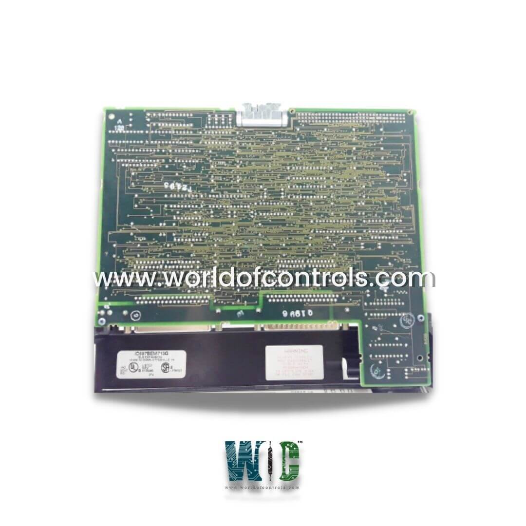
IC697BEM713G - Bus Transmitter Module

IC697BEM713G - Bus Transmitter Module IC697BEM713G - Bus Transmitter Module

World Of Controls understands the criticality of your requirement and works towards reducing the lead time as much as possible.

IC697BEM713G - Bus Transmitter Module is available in stock which ships the same day.

IC697BEM713G - Bus Transmitter Module comes in UNUSED as well as REBUILT condition.

To avail our best deals for IC697BEM713G - Bus Transmitter Module, contact us and we will get back to you within 24 hours.

SPECIFICATIONS

Part No: IC697BEM713G
Manufacturer: General Electric
Module Type: Bus Transmitter
Eff. Data Rate: 500 Kbytes/sec
Allowed Distance of Cable: 50 feet
Discrete Points Available: N/A
Serial Ports: 2
Current Required: 1.4 Amps
Series: Mark I and II
Repair: 3-7 Day
Availability: In Stock
Country of Manufacturer: United States (USA)

Functional Description

IC697BEM713G is a Bus Transmitter Module developed by GE. It is a part of 90-70series. This module is designed to facilitate the expansion of the main CPU rack to accommodate up to seven additional IC697 PLC racks, enabling more I/O modules and increased processing power without the need for a larger central unit. It uses a parallel programming interface, which ensures fast and efficient communication between the PLC and connected programming devices.

Features

  • High Performance Parallel Programming Interface: One of the standout features is its parallel programming interface. This allows for a high-speed connection between the programming device and the PLC system, ensuring smooth programming and system expansion.
  • Bus Expansion Interface: The module facilitates bus expansion, allowing additional IC697 PLC racks to be connected to the main CPU rack. The BTM supports up to 7 expansion racks, which increases the system’s capacity for handling more I/O points and advanced control processes.
  • No DIP Switches: Unlike many traditional modules that require the user to manually configure settings through DIP switches, simplifies the configuration process. The module is software-configured, which reduces setup time and minimizes the possibility of human error.
  • Three LED Indicators for Monitoring: It features three LEDs on the module that provide real-time status updates on the module, programmer port, and expansion port. These LEDs help users diagnose and troubleshoot the system’s functionality quickly.
    • Module OK LED: Indicates whether the BTM configuration has been successfully completed and whether the system expansion racks are polled by the CPU software.
    • Programmer Port Enabled LED: Lights up when the PLC and programming device are successfully communicating, ensuring proper configuration.
    • Expansion Port Enabled LED: Shows whether the BTM is correctly communicating with the Bus Receiver Modules (BRMs) in the expansion racks.

Functions

The primary function is to enable system expansion. It connects the main CPU rack to additional expansion racks, providing additional capacity for handling more I/O points and modules. This expansion is critical for larger systems where the CPU rack alone cannot handle all the required modules. The BTM module is especially useful in environments where scaling up the system is necessary for growing operational needs.

The BTM also provides a high-performance parallel interface to the programming device, enabling quick programming of the expanded system. This parallel interface improves communication speed and ensures efficient data transfer between the CPU and the connected programming device.

Installation and Configuration

  • Preparation: Before installation, ensure that the power is turned off to avoid damage to the equipment during setup.
  • Module Installation: The module occupies a single slot in the main CPU rack. It features two connectors,
    • The top connector is for attaching the programming device.
    • The bottom connector is used for connecting the daisy-chained Bus Receiver Modules (BRMs) that lead to the expansion racks.
  • Software Configuration: Once the module is installed, it must be configured using the MS-DOS or Windows-based programming software. The software configuration process is straightforward and does not require the use of DIP switches, making it a user-friendly process.
  • Power Up and Status Check: After installation, turn the power back on. The Module OK LED should light up once the BTM configuration is complete and the system is polled
  • correctly. The other LEDs will show the communication status with the programmer and expansion racks.

Troubleshooting with Status LEDs

  • Module OK LED: If the LED is off, it indicates that the BTM has not been configured properly or that it has failed to poll the expansion racks. This could be due to a configuration issue or faulty wiring.
  • Programmer Port Enabled LED: This LED helps confirm communication between the programming device and the PLC. If it is off, check the cable connections and ensure the programming software is set up correctly.
  • Expansion Port Enabled LED: This LED confirms the status of the connection to the Bus Receiver Modules (BRMs). If it is blinking or off, verify the wiring between the BTM and the expansion racks.


WOC is happy to assist you with any of your GE requirements. Please contact us by phone or email for pricing and availability on any parts and repairs.

FREQUENTLY ASKED QUESTIONS

What is IC697BEM713G?
It is a Bus Transmitter Module developed by GE.

What is the role of the Bus Transmitter Module?
The BTM enables the expansion of the PLC system by connecting additional expansion racks to the main CPU rack. It also provides a parallel interface for programming the PLC, ensuring fast and efficient communication with the programming device.

What is the maximum distance between the main CPU rack and the expansion racks?
It supports communication between the main CPU rack and up to seven expansion racks, though the distance between racks will depend on the specific system setup and the communication cabling used.

Can I use the module with older GE Fanuc systems?
It is designed for use with the 90-70 series PLCs. It is not compatible with earlier or other series such as Series 90-30. Ensure that your system is compatible with the 90-70 series before attempting to install the module.