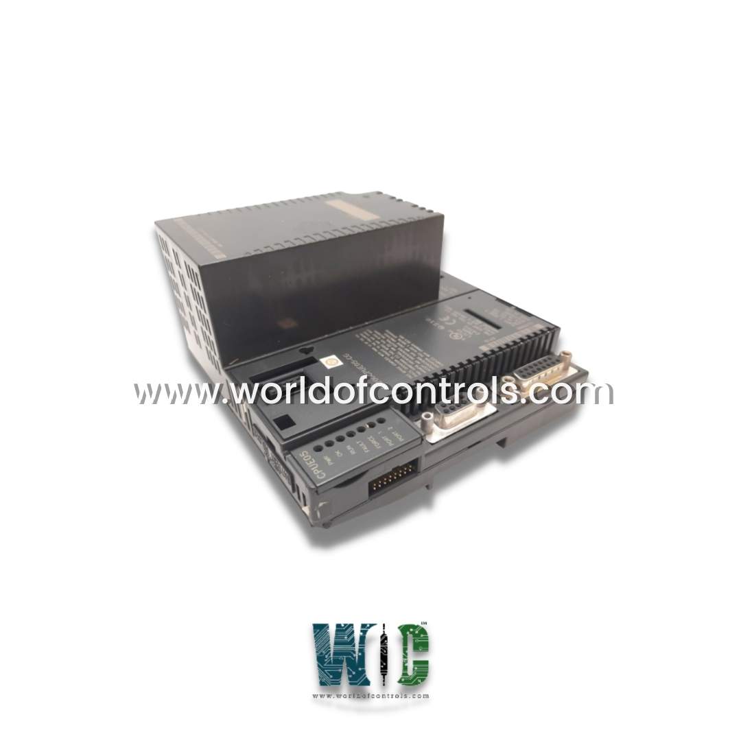
World Of Controls understands the criticality of your requirement and works towards reducing the lead time as much as possible.
IC200CPUE05-CG - CPU Module is available in stock which ships the same day.
IC200CPUE05-CG - CPU Module comes in UNUSED as well as REBUILT condition.
To avail our best deals for IC200CPUE05-CG - CPU Module, contact us and we will get back to you within 24 hours.
Part No.: IC200CPUE05-CG
Manufacturer: General Electric
Country of Manufacture: United States of America (USA)
I/O Capacity: Supports up to 64 modules and 2048 I/O points
Port 1: RS-232, 9-pin female connector.
Port 2: RS-485, 15-pin female D-sub connector
Product Type: CPU Module
Availability: In Stock
Series: VersaMax
IC200CPUE05-CG is a CPU Module developed by GE. It is part of the VersaMax series. It is a powerful CPU module designed by GE for the VersaMax series, intended to serve as the central controller in industrial automation systems. This CPU module is equipped with a variety of features that make it highly versatile and capable of managing a large number of I/O points and modules.
To comply with EN 55011 and FCC Class A radiated emissions, the control system that houses the module must be mounted in a metal enclosure if three or more modules are used. All surfaces of the enclosure must be grounded to adjacent surfaces to ensure electrical conductivity. External wiring must be routed through metal conduit or an equivalent, with the conduit securely mounted to the enclosure for proper grounding. Additionally, during installation, operation, or maintenance, personnel must ensure electrostatic discharge (ESD) is prevented by using grounded ESD straps or similar measures.
The module is specifically designed for use with the VersaMax system. Since the system components are considered open equipment with accessible live electrical parts, they must be installed within an enclosure that meets safety standards. At a minimum, the enclosure must provide protection against solid objects as small as 12mm, equating to a NEMA/UL Type 1 or IEC60529 IP20 rating, which ensures a pollution degree 2 environment. For further installation instructions, refer to the VersaMax Modules, Power Supplies, and Carriers User's Manual, GFK-1504.
Before installation, it is crucial to carefully inspect all shipping containers for any damage. If the equipment shows signs of damage, it is important to notify the delivery service immediately and save the shipping container for inspection. After unpacking, record all serial numbers for inventory and future reference. It is advisable to retain the shipping containers and packing material for potential future transportation needs.
The module can be mounted on either a horizontal or vertical DIN rail. When mounting on a vertical DIN rail, ensure the CPU module is placed at the bottom. The CPU and connecting carriers must be installed on the same section of 35mm (1.38in) x 7.5mm (.3in) DIN rail, which should be 1mm (.04in) thick. The recommended material is steel, and the rail must be electrically grounded for proper EMC protection. The rail must have a conductive, corrosion-resistant finish. It is essential to install the DIN rail with screws spaced approximately 15.24cm (6in) apart for vibration resistance. The rated thermal specifications for the CPU module depend on maintaining a clearance of 50.8mm (2in) above and below the equipment and 25.4mm (1 inch) to the left of the CPU module. Additional clearance is needed for power wiring, serial ports, and Ethernet cables.
It comes with a built-in Ethernet interface, enabling communication over a 10BaseT network. The module supports both half-duplex and full-duplex operation, with automatic detection of the mode. It can operate with 10/100 hubs, allowing communication on a network with devices running at up to 100Mb.
The Ethernet interface facilitates several functions:
The WOC team is always available to help you with your Mark I and II requirements. For more information, please contact WOC.
What is IC200CPUE05-CG?
It is a CPU module developed by GE under VersaMax series.
What is the function of the built-in Ethernet interface?
The built-in Ethernet interface allows to communicate over a 10BaseT network, supporting both half- and full-duplex operations. It enables the CPU to communicate with host computers and other GE Fanuc PLCs, facilitating data access and system integration.
Can the module automatically switch communication modes?
Yes, when either serial port is used for RTU operations, the module automatically switches to SNP slave mode. Additionally, if the CPU is in Stop mode and configured for Serial I/O, Port 1 will automatically revert to SNP slave mode.
What is the purpose of the Ethernet Restart pushbutton?
The Ethernet Restart pushbutton allows users to forcibly change the mode of Port 1 if it is configured for CPU use. The port will remain in the forced mode until the PLC is power cycled or the pushbutton is pressed again, providing a quick way to reset or adjust the port’s operation.