World Of Controls understands the criticality of your requirement and works towards reducing the lead time as much as possible.
IC200ETM001C - Expansion Connector is available in stock which ships the same day.
IC200ETM001C - Expansion Connector comes in UNUSED as well as REBUILT condition.
To avail our best deals for IC200ETM001C - Expansion Connector, contact us and we will get back to you within 24 hours.
Part No.: IC200ETM001C
Manufacturer: General Electric
Country of Manufacture: United States of America (USA)
Product Type: Expansion Connector
Number of Racks: 8 per Station
Number of Modules: 8 per Rack
I/O Data: 1024 bytes
Ethernet Network Data Rate: 10/100 Mbits
Ethernet Duplex: Full/Half Auto-Detect
Availability: In Stock
Series: VersaMax
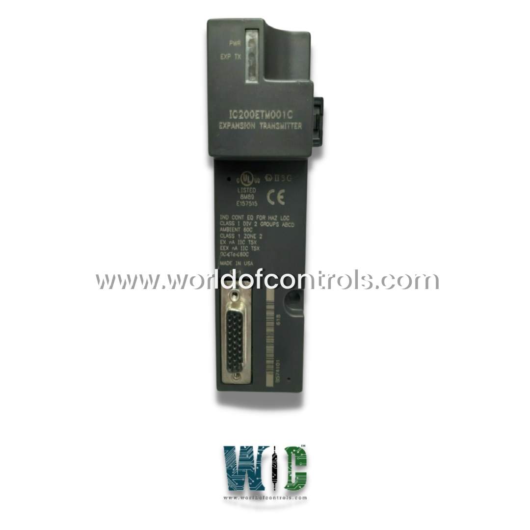
IC200ETM001C is an Expansion Connector developed by GE. It is a part of VersaMax PLC system, enabling them to support up to seven additional racks. Each additional rack can accommodate up to eight input/output modules, including field bus communication modules, significantly enhancing the PLC’s capacity to manage more inputs and outputs. The module features a 26-pin female connector at the front, which is used to link to expansion receiver module. Additionally, it includes a 16-pin male serial port located at the upper left corner, which serves as a serial programming port for uploading firmware updates to the adjacent Network Interface Unit (NIU).
A standout feature of the module is its high-speed expansion interface, which ensures efficient communication between the main CPU or NIU and the expansion racks. The module includes two LED indicators: the Power LED and the EXP TX LED. The Power LED indicates that the module is receiving 5V DC from the CPU or NIU; if the LED is off, it suggests that either the module is disconnected or there is a loss of power from the CPU. The EXP TX LED blinks when there is active communication between the expansion transmitter and bus receiver modules. If no communication is detected, the LED remains off, helping users identify potential connectivity issues.
The module is compatible with two types of expansion receiver modules: the Isolated Receiver Module (ERM001) and the Non-Isolated Receiver Module (ERM002). The ERM001 allows for a maximum expansion cable length of 15 meters, which is ideal for compact installations, while the ERM002 can support a much longer cable length of up to 750 meters, making it suitable for larger, more complex systems. The flexibility in cable length and the option to choose between isolated and non-isolated modules offer greater versatility in designing and expanding PLC systems for various industrial environments.
Installing the module is a straightforward process. The module is mounted on a 35mm x 7.5mm DIN rail, and the rail must have an unpainted finish for proper grounding. It is recommended that the DIN rail be securely fastened to a panel using screws spaced six inches apart for stability. Once mounted, the module is connected to the left side of the VersaMax CPU or NIU module. The rack ID (1–7) for the expansion module is selected using a rotary switch, which can be accessed through a small door located on the upper left corner of the module. After configuring the rack ID, the power supply is connected to the expansion receiver, and the LEDs are checked to confirm proper operation.
The module initially operates at a default data rate of 250 Kbits/second to accommodate the maximum cable length. However, if the total cable length is less than 250 meters and there are no ERM002 modules in the system, the data rate can be adjusted to 1 Mbit/second to improve performance. In systems using an NIU I/O station, the data rate is fixed at 250 Kbits/second and cannot be adjusted. This ensures stable and reliable communication, regardless of the specific configuration of the expansion system.
Maintaining and removing the module is simple and efficient. Before removing the module, it is essential to power off the system and disconnect the power supply from the expansion receiver module. The module can then be slid away from the other modules on the DIN rail, after which it can be lifted off using a screwdriver if necessary. This tool-free installation and removal process ensure that the module can be easily replaced or serviced without requiring specialized equipment.
The WOC team is always available to help you with your Mark I and II requirements. For more information, please contact WOC.
What is IC200ETM001C?
It is an Expansion Connector developed by GE under VersaMax series.
Can I adjust the data rate of the module?
Yes, the module initially operates at a data rate of 250 Kbits/second, which is suitable for the maximum cable length. However, if the total cable length is less than 250 meters and no ERM002 modules are used, the data rate can be adjusted to 1 Mbit/second for better performance. In systems with an NIU I/O station, the data rate remains fixed at 250 Kbits/second.
How do I remove the module from the DIN rail?
To remove the module, power off the system and disconnect the power supply from the expansion receiver module. Slide the expansion module away from the other modules on the DIN rail. Then, using a screwdriver, unscrew and lift the module off the DIN rail.
Is special tooling required for installation or removal?
No, special tools are not required for the installation or removal of the module. It easily snaps into place on the DIN rail, and a screwdriver can be used for removal when necessary.