SPECIFICATIONS
Part No.: IC200CHS022
Manufacturer: General Electric
Country of Manufacture: United States of America (USA)
No. of channels: 4
Voltage Range: 5 V nominal
RTD Types: Platinum, Copper, Nickel, Nickel/Iron
Update Rate: 210 ms
Power Consumption: 125 mA from +5V bus
Product Type: I/O Carrier Module
Availability: In Stock
Series: VersaMax
Functional Description
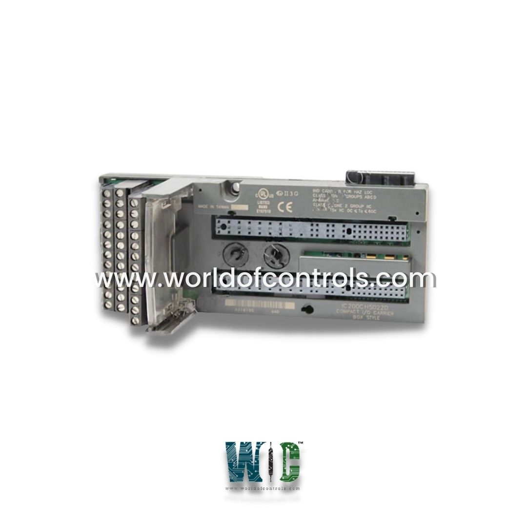
IC200CHS022 is an I/O carrier module developed by GE. It is part of the VersaMax series. It is a compact, box-style I/O Carrier module manufactured by GE Fanuc as part of the GE Versamax series, designed to support the mounting, backplane communications, and field wiring for a single Input/Output (I/O) module.
Product Features
- IEC Box-Style Terminals: Features 36 IEC box-style terminals, ensuring robust and secure connections for industrial wiring. These terminals are critical for maintaining the integrity of connections within a system, especially in environments where vibration or external disturbances might otherwise cause issues. The secure nature of these connections helps ensure that the system remains operational without interruption.
- Versatility for Automation Tasks: The I/O carrier module supports up to 32 I/O points and four common power connections, providing versatility in various automation tasks. This capacity makes the module suitable for a wide range of applications, from basic control systems to more complex, multi-point control environments.
- Compact Design: Designed with a compact form factor, it measures just 66.8 mm x 70 mm x 163.5 mm. This compact size makes it ideal for installations where space is limited, enabling it to fit into tight enclosures or cabinets without taking up valuable real estate. Despite its small size, the module does not compromise on performance, making it a powerful solution for control systems.
- DIN Rail Mounting: The module is designed for easy installation on a standard 7.5 mm x 35 mm DIN rail, a widely accepted mounting standard in industrial environments. This quick installation feature saves time during setup, allowing the module to snap securely into place. To ensure optimal electromagnetic compatibility (EMC) protection, it is recommended that the DIN rail be electrically grounded and have a conductive, corrosion-resistant finish, preferably unpainted.
Temperature Range and Ventilation Requirements
- Designed to operate in ambient temperatures ranging from 32oF to 140oF (0oC to 60oC), which covers a broad range of industrial environments. Proper ventilation is critical to prevent overheating, so the module should be installed with at least 1 inch of horizontal spacing and 2 inches of vertical spacing. This spacing ensures sufficient airflow around the module, allowing it to maintain stable performance under varying temperature conditions.
- A foldable printed wiring card is included with the module, which can be inserted into the built-in card holder for organized wiring management. The card holder is designed to be pulled back during operation, providing easy access to the wiring while maintaining the module's functionality. This feature helps keep wiring organized and readily accessible for maintenance or troubleshooting.
- For applications that require high resistance to mechanical vibration and shock, the module should be panel-mounted in addition to being mounted on the DIN rail. This dual mounting option ensures stable and secure performance even in harsh industrial environments, such as those with significant vibration or mechanical stress.
Installation Procedure
- Easy-Keying Dials: Easy-keying dials that simplify installation by matching the keying at the base of the module. This design prevents incorrect module placement, ensuring that the right components are installed in the correct positions without the need for additional tools or effort.
- Male-Female Connectors: The module comes equipped with male-female connectors that facilitate quick backplane connections. This tool-free design makes it easier to connect the module to the system, saving time and reducing the complexity of installation. No additional tools or cables are required for backplane connections, simplifying the setup process.
- Module Latch Hole: A latch hole is integrated into the design, ensuring that the module is securely fastened to the carrier. This feature provides stability during operation and prevents the module from becoming loose or disconnected, particularly in environments subject to mechanical vibrations or other external factors.
Wiring Flexibility
- The carrier is designed to accommodate either single-wire or double-wire setups, depending on the requirements of the application. In a single-wire setup, the module supports a wire cross-section range from 0.36 mm² to 2.1 mm2. This range ensures flexibility in handling various wire sizes and types for different system configurations.
- For applications that require double-wire setups, it supports a maximum cross-section of 0.86 mm² per terminal. This feature enables the module to support more complex wiring configurations, expanding its flexibility for various use cases in automation systems.
- To ensure optimal conductivity and connection integrity, only solid or stranded copper wires should be used. This specification helps to maintain the reliability of the electrical connections, ensuring that the system remains operational over time and under varying environmental conditions.
The WOC team is always available to help you with your Mark I and II requirements. For more information, please contact WOC.
Frequently Asked Questions
What is IC200CHS022?
It is an I/O carrier module developed by GE under VersaMax series.
What are the dimensions of the module?
It measures 66.8 mm x 70 mm x 163.5 mm, making it a compact solution suitable for space-constrained industrial environments.
How is the module installed?
The module is designed to easily snap onto a 7.5 mm x 35 mm DIN rail. For maximum stability and protection against electromagnetic interference (EMI), the DIN rail should be electrically grounded and have a conductive, corrosion-resistant finish. Additionally, for environments with high mechanical vibration and shock, it is recommended to also panel-mount the carrier.
What type of wiring does it support?
The carrier supports both single-wire and double-wire setups per terminal. The single-wire cross-section range is 0.36 mm2 to 2.1 mm2, while the maximum double-wire cross-section is 0.86 mm2. Only solid or stranded copper wires should be used.
