SPECIFICATIONS
Part No.: IC200ALG320
Manufacturer: General Electric
No. of channels: 4 single-ended, one group
Voltage Range: 18 - 30 VDC
Current Range: 4 - 20 mA
Update Rate: 0.3 ms
LED Indicators: FLD PWR, OK
Power Consumption: 50 mA from +5V bus
Backplane Support: PCI and High-Speed Serial
Product Type: Analog Output Module
Availability: In Stock
Series: VersaMax
Functional Description
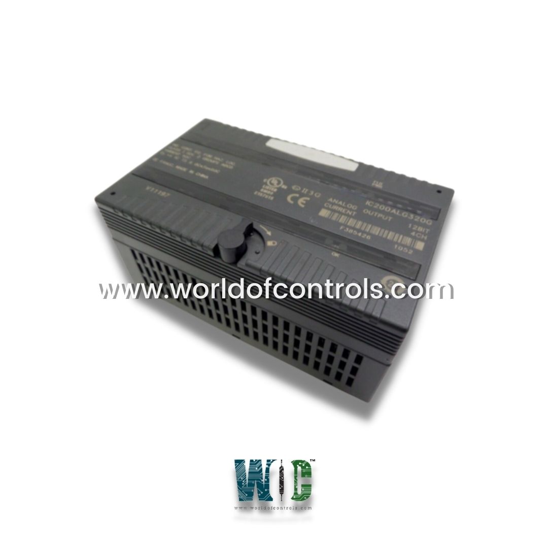
IC200ALG320 is an analog output module developed by GE. It is a 4-Channel, 12-Bit Current Analog Output module from the GE Fanuc VersaMax Series, designed to provide reliable and precise current outputs for industrial automation systems.
Features
- Current Outputs: The module provides four analog current-sourcing outputs, each capable of delivering a current range of 4mA to 20mA. This makes it suitable for applications requiring precise current control, such as driving actuators, control valves, or other industrial devices.
- Over-Range Capability: The module offers a slight over-range capability, allowing each channel to deliver approximately 20.38mA of output current. This over-range feature provides additional flexibility in applications where higher current levels might occasionally be required.
- State Retention on Power Loss: Designed to handle unexpected interruptions in backplane power or communications. A jumper on the module allows users to choose whether the outputs should retain their last known state or revert to a default state in such scenarios. The outputs will maintain their current state until new output data is received or the field power is disconnected.
- Load Resistance Considerations: The minimum load resistance per channel is determined by factors such as ambient temperature, external voltage, and the module's installation configuration, including its position on the DIN rail. Users should consider these factors to ensure optimal performance and avoid issues related to insufficient load resistance.
Recommended Wiring: Shielded twisted-pair cables help reduce noise and ensure signal integrity, which is crucial in environments with high electromagnetic interference (EMI).
LED Indicators
The module is equipped with LED indicators for easy monitoring of its status:
- The green FLD power LED indicates the presence of user-side power for the analog field-side circuits.
- The green OK LED lights up when backplane power is detected, confirming that the module is powered and operational.
Configuration Parameters
- State-Holding Configuration: A jumper on the module allows configuration of output behavior if backplane power or communications are interrupted, or if the PLC is stopped. In such events, outputs can either:
- Hold their last state to maintain the current process, or
- Default to a predetermined state to ensure safety or reset processes.
- External User Power: Uninterrupted external user power is required to maintain the module's output state in the event of communication or power issues. Outputs will stay in their last state or default state until the module receives new output data or until field power is removed.
Preinstallation Check
- Inspect Shipping Containers: Carefully check all containers for any visible damage. If damage is found, notify the delivery service immediately and keep the damaged container for inspection.
- Record Serial Numbers: After unpacking, document all serial numbers for reference.
- Save Packing Materials: Retain all shipping containers and packing materials in case future transport or shipment of the system is required.
Compatibility
- The module is compatible with the initial release of VersaMax CPUs and NIUs (Network Interface Units).
- Modules installed in expansion racks must be of revision C or later to ensure proper functionality and compatibility with the VersaMax system.
Installation in Hazardous Locations
- The Analog Output Module is specifically designed to operate safely in hazardous environments, classified as Class I, Division 2, Groups A, B, C, & D. These guidelines ensure the module is only used in suitable environments and prevent risks associated with explosive atmospheres.
- For use in Class I, Division 2 areas, this module is safe only in groups A, B, C, and D or in non-hazardous locations. Using it in other hazardous areas is not recommended and could lead to unsafe conditions. To avoid explosion risks, component substitution within the module must be avoided; replacing components with unapproved parts can compromise the module’s suitability for hazardous locations.
- Power safety is essential during any maintenance or wiring in hazardous locations. Always turn off the power before handling the module. This minimizes the risk of sparking, which could be hazardous in volatile environments. Furthermore, when operating in such areas, do not disconnect the equipment unless the power has been shut off or it is confirmed that the area is non-hazardous. Disconnecting live equipment in hazardous areas could lead to explosions.
- These precautions ensure functions safely in hazardous locations, providing both effective performance and adherence to strict safety standards.
The WOC team is always available to help you with your Mark I and II requirements. For more information, please contact WOC.
Frequently Asked Questions
What is IC200ALG320?
It is an analog output module developed by GE under VersaMax series.
What type of wiring is recommended for connecting the module?
It is recommended to use shielded twisted-pair cables for all connections involving the card. This helps reduce noise and ensures signal integrity, particularly in environments with high electromagnetic interference (EMI).
Is the module compatible with all VersaMax CPUs?
Yes, it is compatible with the original release of VersaMax CPUs and Network Interface Units (NIUs).
What factors influence the minimum load resistance per channel?
The minimum load resistance per channel is influenced by the ambient temperature, external voltage, and the module's installation configuration, including its position on the DIN rail.
