SPECIFICATIONS
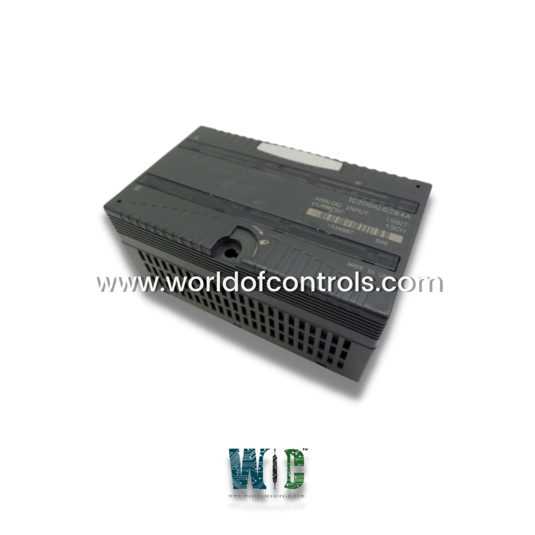
Part No.: IC200ALG264A
Manufacturer: General Electric
No. of channels: 15 single-ended, one group
Current Range: 4 - 20 mA, 0 - 20 mA
Update Rate: 7.5 ms
Input Filter Response: 24 Hz +/-20%
Power Consumption: 100 mA from +5V bus
Country of Manufacture: United States of America (USA)
Product Type: Analog Input Module
Availability: In Stock
Series: VersaMax
Functional Description
IC200ALG264A is an Analog Input Module developed by GE. It is a 15-Channel, 15-Bit Current Analog Input Module developed as part of its VersaMax Series, providing an interface for up to 15 current inputs. This module is powered directly from the backplane power supply, eliminating the need for an external power source. However, power for the user’s transceivers must still be provided externally. This module features single-ended analog inputs that share a common return and is rated for a 250 VAC continuous duty cycle, ensuring reliable performance.
Features
- Input Range and Jumper Selection: Offers two input ranges: 4-20 mA and 0-20 mA, which can be selected via a jumper on the carrier terminals. This allows users to configure the input range based on specific application requirements. If the jumper is not installed, the module can only accept 4-20 mA signals. This flexibility in configuration makes it suitable for various current input applications.
- High-Resolution Analog Conversion: This module includes a 15-bit analog-to-digital converter, providing high resolution and precise measurement for each input channel. This level of resolution is ideal for applications requiring accurate and detailed data acquisition from analog sources.
- Software Configurability: The module can be configured through software to hold the last state or return to a default state in case of a power loss. This configurable software ensures that the module can maintain control and provide reliable output based on specific operational needs, adding flexibility and robustness to the module’s functionality.
- Diagnostic Features: This module includes several diagnostic capabilities, such as loss of internal power error reporting for field-side circuits and open wire detection on each channel when in 4-20 mA mode. These diagnostics enable real-time monitoring and reporting of errors, which can aid in troubleshooting and maintaining system integrity.
- Status LED Indicator: A green LED indicator on the module lights up when backplane power is present and internal field power is functioning correctly. This LED provides a quick visual status check for operators to confirm power integrity.
Cable Shielding and Connections
- For analog channel connections, it is recommended to use shielded twisted pair cables. Proper grounding of the cable shield is essential for reducing electrical noise and ensuring signal accuracy. Ideally, the shield should be grounded at the source device; however, if grounding at the source is not feasible, it can be grounded at the I/O module.
- If the module is installed on a Terminal-style I/O Carrier (e.g., CHS001, 002, or 005), shield connections can be made on an Auxiliary I/O Terminal that is attached to the I/O carrier. For Compact Terminal-style I/O Carriers (e.g., CHS022, 025), the Auxiliary I/O Terminal should be mounted nearby for effective grounding. When using an Auxiliary I/O Terminal, ensure it is properly grounded to maintain signal integrity.
- If the module is installed on a Connector-style I/O Carrier (e.g., CHS003), the cable shield can be connected directly to an Interposing Terminal (CHS011, 012, 015). In this setup, a shielded interposing cable is recommended between the Interposing Terminal and the Connector Base for enhanced signal protection. Additionally, custom shielded cables can be made with a Connector kit (ACC302) or by wrapping a custom shield braid around standard interposing cables (e.g., CBL105, 110, 120, 230). It is important to ground the braid if this approach is used to maximize shielding effectiveness.
The WOC team is always available to help you with your Mark I and II requirements. For more information, please contact WOC.
Frequently Asked Questions
What is IC200ALG264A?
It is an Analog Input Module developed by GE under VersaMax series.
How does the module receive power?
The module receives power directly from the backplane power supply and does not require any external power source for its operation. However, an external power source is needed for the user’s transceivers.
What types of inputs does the module support?
It supports single-ended analog inputs with a configurable input range of 4-20 mA or 0-20 mA. This range can be selected using a jumper on the carrier terminals.
What is the significance of the 15-bit resolution?
The 15-bit resolution allows for precise measurement and data acquisition, which is crucial in applications where accuracy is important, such as in process control and automation systems.
Can the module handle both current and voltage inputs?
No, the module is specifically designed for current inputs (4-20 mA or 0-20 mA). It does not support voltage inputs.
