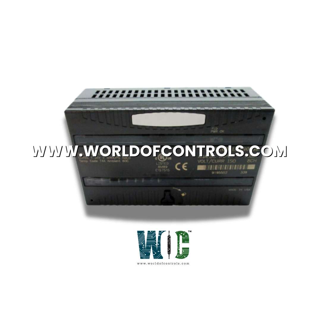
IC200ALG240 - Analog Input Module

IC200ALG240 - Analog Input Module IC200ALG240 - Analog Input Module

World Of Controls understands the criticality of your requirement and works towards reducing the lead time as much as possible.

IC200ALG240 - Analog Input Module is available in stock which ships the same day.

IC200ALG240 - Analog Input Module comes in UNUSED as well as REBUILT condition.

To avail our best deals for IC200ALG240 - Analog Input Module, contact us and we will get back to you within 24 hours.

SPECIFICATIONS

Part No.: IC200ALG240
Manufacturer: General Electric
Country of Manufacture: United States of America (USA)
No. of Inputs: 8 isolated
Voltage Range: -10 to +10 volts DC
Current Range: 4 - 20 mA
Update Rate: 20 ms
Input Filter Response: N/A
Power Consumption: 15 mA from +5V bus
Product Type: Analog Input Module
Availability: In Stock
Series: VersaMax

Functional Description

IC200ALG240 is an analog input module developed by GE. It is part of the VersaMax series. It is designed to provide robust and precise analog signal processing. This module is capable of interfacing with up to eight analog devices, each delivering a distinct input signal. excels in applications requiring high-resolution data acquisition, offering a 16-bit resolution for precise and reliable analog-to-digital conversion.

Features

  • Eight Isolated 4-20mA Current Input Channels: Each channel can operate independently, allowing for connections to a variety of analog devices.
  • 16-Bit Converter Resolution: Offers high-precision analog-to-digital conversion, ensuring the data is detailed and reliable.
  • Open Wire Detection: Detects and alerts if a wire becomes disconnected, improving fault detection and system reliability.
  • High-Accuracy Factory Calibration: The module is calibrated to high standards during manufacturing, ensuring consistency in measurement accuracy.

Software-Configurable Features

  • Each channel can be configured for either 4-20mA current inputs or ±10V voltage inputs, providing flexibility in handling different signal types.
  • A configurable input filter helps reject AC noise, particularly effective in noisy environments, thereby improving signal quality.
  • Allows the module to maintain or reset input values upon certain events or power cycles.
  • Default input values can be set per channel, providing predictable behavior in case of signal loss.
  • Diagnostics for Under-Range and Over-Range Conditions, Each channel can be set to monitor specific thresholds, improving early detection of potential issues.
  • Per-channel alarm configurations allow for precise monitoring and quick response to abnormal conditions.
  • Configurable scaling per channel helps adjust readings to match desired output ranges, enhancing ease of integration.
  • The module can be recalibrated in the field, ensuring ongoing accuracy without the need for factory recalibration.

LED Indicators

  • The LED indicators on this analog input module provide essential visual cues for monitoring power status and operational health, enabling users to quickly assess the module’s condition at a glance.
  • FLD PWR LED: Field and Backplane Power Status
    • The green FLD PWR LED signifies the presence of both backplane power and field power for the analog field-side circuits. When both power sources are active and functioning correctly, this LED remains illuminated. If either backplane power or field power is absent, the FLD PWR LED turns off, alerting operators to potential power issues that could impact module performance. This feature provides an immediate indication of power integrity, helping to ensure reliable operation of the connected analog circuits.
  • OK LED: Module Status and Diagnostics
    • The OK LED serves as a multi-functional status indicator for the module, changing colors and blinking patterns to communicate different operating states:
    • Solid Green: This indicates that the module is functioning normally, with all systems operational and no detected issues.
    • Flashing Green: A flashing green light indicates that the module is either in boot mode (initializing) or updating firmware. This state generally occurs during startup or when a firmware update is in progress.
    • Flashing Amber: When the LED flashes amber, it signals a self-diagnostic error. This color and pattern indicate that the module has encountered an internal error and may require inspection or troubleshooting. The flashing amber light helps operators quickly identify and address potential issues before they affect overall system performance.

Cable Shield Connections

  • When the module is mounted on a Terminal-style I/O Carrier or a Compact Terminal-style I/O Carrier, the cable shield can be directly connected to the carrier itself. This straightforward connection helps maintain signal quality by grounding the cable shield directly to the carrier, effectively reducing noise and interference. By using this approach, users ensure that the analog signal remains stable and less prone to degradation, which is especially valuable in high-precision applications.
  • If the module is installed on a Connector-style I/O Carrier, a slightly different approach is required to establish the shield connection. In this case, the cable shield can be connected to an Interposing Terminal. For this setup, a shielded interposing cable must be used between the Connector-style I/O Carrier and the Interposing Terminal, which is available separately. This shielded cable serves as a bridge between the carrier and the interposing terminal, helping to maintain continuous shielding throughout the connection. This configuration is ideal for environments with higher noise levels, as it provides added protection against electromagnetic interference.
  • In cases where multiple shield connections are needed, an Auxiliary I/O Terminal can be added to the Interposing Terminal. This additional terminal provides more points for connecting cable shields, offering flexibility for complex setups that require multiple shielded connections. By adding an Auxiliary I/O Terminal, users can ensure all shielded cables are grounded effectively, further reducing the potential for signal interference across different channels.

Diagnostics

The Analog Input Module is equipped with a comprehensive set of diagnostic features to monitor input values and detect faults. These diagnostics ensure early detection of issues, which allows operators to take corrective action and maintain system stability. Here is an overview of each diagnostic feature:

Over-Range Detection
The module reports an Over-Range fault if an input value exceeds certain thresholds. Specifically, it triggers if the input signal is greater than approximately +12.5 volts for voltage channels or 25mA for current channels. This alert helps protect the module from potential damage due to excessively high input levels and ensures that data accuracy is not compromised by signals outside the intended measurement range.

Under-Range Detection
An Under-Range fault is reported when an input value falls below specified minimums. This fault is triggered if the input signal is approximately 0mA on a current input channel or -12.5 volts on a voltage input channel. Detecting under-range conditions allows the module to flag any potential connectivity or sensor issues that may cause input values to drop below the expected range.

Open Wire Detection
The Open Wire fault is a diagnostic specifically for current input channels. This fault is reported when the low end of the range is configured at or above approximately 2.0mA, but the input does not detect any current flow. This condition indicates a possible open or disconnected wire, allowing operators to identify and resolve wiring issues before they impact the overall system performance.

Loss of Field Power Supply Detection
The module reports a Loss of Field Power fault if it detects that field power is not present. This fault is also indicated by the FLD PWR LED turning off. In this scenario, the module’s inputs will default to a state specified by the user’s configuration settings. Detecting a loss of field power is critical to maintaining the integrity of input signals and ensuring that operators are aware of power supply issues promptly.

High Limit Alarm Detection
A High Alarm fault is triggered if an input value meets or exceeds a specified high limit, defined by the "Alarm High" configuration parameter. This high limit alarm helps users monitor critical thresholds and identify when input values are approaching or exceeding acceptable operational limits, allowing preventive actions to be taken before issues arise.

Low Limit Alarm Detection
Similarly, the module reports a Low Alarm fault if an input value is less than or equal to the configured "Alarm Low" parameter. This diagnostic is useful for monitoring minimum operational thresholds and identifying conditions where input values fall below desired levels, which could indicate issues such as sensor drift or signal interference.

Non-volatile Memory Fault
During field recalibration, the module checks for a non-volatile memory fault. If a fault in the non-volatile memory is detected, it is reported immediately, alerting operators to issues in memory that could impact calibration settings or module performance. This diagnostic is essential for maintaining accurate recalibration data and ensuring the reliability of stored configuration settings.

Compatibility

The Analog Input Module is designed to integrate seamlessly with various network interface units (NIUs) and programmable logic controllers (PLCs) within the VersaMax series, making it highly versatile and adaptable for complex automation environments. Below is a breakdown of the compatibility requirements and version specifications for optimal performance and configuration:

  • This module is fully compatible with PLC CPU firmware version 1.20 or later. Ensuring that the PLC CPU firmware is updated to this version or newer is essential for achieving stable communication and taking advantage of the module’s full range of features. The compatibility with updated firmware versions enhances the module’s performance and helps avoid potential compatibility issues with older PLC models.
  • The module is compatible with EtherNet NIU EBI001 in all versions, providing flexible connectivity options across Ethernet networks. This allows for reliable data transmission and control over Ethernet, making it suitable for systems that require network-based communication for remote monitoring and control.
  • For the Genius NIU GBI001, the module requires firmware version 1.10 or later. However, to enable software configuration capabilities, NIU version 2.0 or above is necessary. This compatibility ensures that the module can integrate into Genius networks with advanced configuration options, allowing for enhanced customization in settings and diagnostics.
  • When used with Profibus NIU PBI001, the module requires firmware version 1.10 or later. Similar to the Genius NIU, version 2.0 or above is necessary for software configuration capabilities. This compatibility allows users to deploy the module within Profibus networks, providing seamless integration and configurable options for Profibus-based automation systems.
  • The module also supports DeviceNet NIU DBI001 with firmware version 2.10 or later, making it compatible with DeviceNet networks for industrial automation. DeviceNet compatibility provides robust connectivity for systems utilizing this protocol, ensuring reliable data exchange and system flexibility in environments where DeviceNet is the preferred communication standard.

The WOC team is always available to help you with your Mark I and II requirements. For more information, please contact WOC.

Frequently Asked Questions

What is IC200ALG240?
It is an analog input module developed by GE under VersaMax series.

How are alarm levels and default values configured?
These settings can be adjusted via software, allowing users to tailor the module’s performance to their specific application needs.

Can the board be used in systems with different filter frequencies?
Yes, the module supports filter frequencies of 50Hz and 60Hz, with corresponding update rates of 20 milliseconds and 16.7 milliseconds, respectively.