SPECIFICATIONS
Part No.: DS200VPBLG1AFF
Manufacturer: General Electric
Country of Manufacture: United States of America (USA)
Manual: GEI-100227
Number of Power Bugs: 10
Exciter Connection: 34-Pin Ribbon Connector
Number of Test points: 60 Spring-Loop
Temperature: 0 to 60 oC
Product Type: VME Backplane Board
Availability: In Stock
Series: LCI
Functional Description
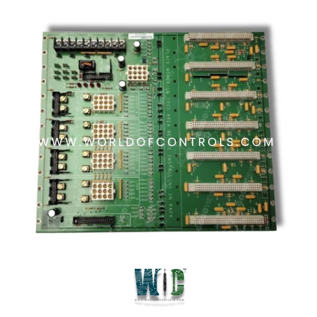
DS200VPBLG1AFF is a VME Backplane Board developed by GE. It is a part of LCI series. Its multi-layer design, expandable slot configuration, and advanced signal monitoring features make it an essential part of industrial power and drive systems.
Features
- Multi-Layer Board Design: Separates digital and analog power planes to minimize interference and improve signal integrity. Equipped with bypass capacitors at each power connection for stable power distribution.
- Slot and Section Configuration: Installed within a 13-slot chassis to accommodate various system modules. Comprises two sections:
- J2 Section: Supports the DSPC Board, I/O Extenders, up to three FCGD (Gate Distribution and Status) Boards, and one Exciter Board. Two additional slots are available for expansion.
- J3 Section: Used for external connections, particularly when space constraints prevent connections on the board fronts. This section also facilitates power distribution.
- Exciter Connection and Ribbon Connector: Features a 34-pin ribbon connector for Exciter Board connections. Ensures seamless communication between exciter components and the backplane.
- Tachometer Settings and Configuration: Supports two main tachometer settings:
- Twelve-Pin Terminal Block: Includes multiple nomenclature points, such as E0V2 (tach power supply V1 - common node choke) and E1V1 (tach power supply V1 + common mode choke).
- Jumpers: Used for configuring tachometer signal paths. These jumpers ensure proper data flow through the backplane.
- Test Points for Signal Analysis: Contains 60 spring-loop test points that allow engineers to monitor digital and analog signals. These test points provide access to:
- The three-phase AC input power signals.
- Positive and negative DC outputs for real-time voltage monitoring.
- Factory-assigned test points (55, 62-118) for diagnostics and calibration.
- Power and System Integration: Utilizes pluggable connections to reduce wiring errors and improve maintenance efficiency. Ensures high-speed data transmission between system components within the LCI control framework.
Diagnostics and I/O Connectivity
- The diagnostics connector allows engineers to observe system performance, ensuring that all connected modules function correctly.
- By accessing diagnostic data, maintenance personnel can quickly identify malfunctions within the control system. This reduces downtime and enhances system reliability.
- The diagnostics connector provides a direct I/O interface with the J1 processor, which serves as a central processing unit for the system. This connection ensures that diagnostic data is efficiently processed, enabling automated alerts for system irregularities.
- The connector can be interfaced with specialized diagnostic tools or software for comprehensive system analysis.
Installation and Removal Considerations
Preparation
Before installing the VME Backplane Board, ensure the system is completely powered off to eliminate electrical hazards. It is recommended to use an anti-static wrist strap to prevent electrostatic discharge (ESD) from damaging sensitive components. Make sure that all capacitors have discharged to avoid residual voltage that may cause issues during installation.
Step-by-Step Installation Process
- Carefully align the edge connectors of the board with the slots on the chassis where it will be mounted. It is designed to fit into a 13-slot chassis, with J2 and J3 sections configured for specific connections. Ensure the board is positioned so that it will easily slide into the corresponding slots without resistance.
- Once the board is aligned and in position, gently insert the edge connectors into the slot, ensuring that they are properly seated. Secure the board with the necessary screws to hold it firmly in place. Use a non-magnetic screwdriver to avoid damage to the components. Do not overtighten, as this can cause damage to the board or the chassis.
- Attach the ribbon cables to the board. If no pull-tabs are available, grasp the connector housing gently and pull it into place without twisting. If pull-tabs are present, carefully use them to connect the ribbon cables to the board. Double-check that all cable connections are firm and that there is no sign of loose connections, as this can cause signal transmission errors.
- Once the board is securely mounted and connected, power up the system. Run a diagnostic check to verify that the board and all connected components are functioning correctly. Check for any error codes or fault indicators to confirm that the installation was successful.
The WOC team is always available to help you with your LCI requirements. For more information, please contact WOC.
Frequently Asked Questions
What is DS200VPBLG1AFF?
It is a VME Backplane Board developed by GE under the LCI series.
What should I do if the ribbon cables do not have pull-tabs?
If the ribbon cables do not have pull-tabs, you should gently grasp the connector housing and pull it straight out, making sure not to twist or apply excessive force. This helps avoid damage to the cable or connectors.
What is the role of the diagnostics connector on the board?
The 26-pin discrete diagnostics connector provides input/output connections to the J1 processor. It allows for efficient system diagnostics and troubleshooting, enabling engineers to monitor system performance and quickly identify faults or irregularities.
