SPECIFICATIONS
Part No.: DS200TCRAG2ABC
Manufacturer: General Electric
Country of Manufacture: United States of America (USA)
Technology: Surface mount
Product Type: Relay Output Board
Availability: In Stock
Series: Mark V
Functional Description
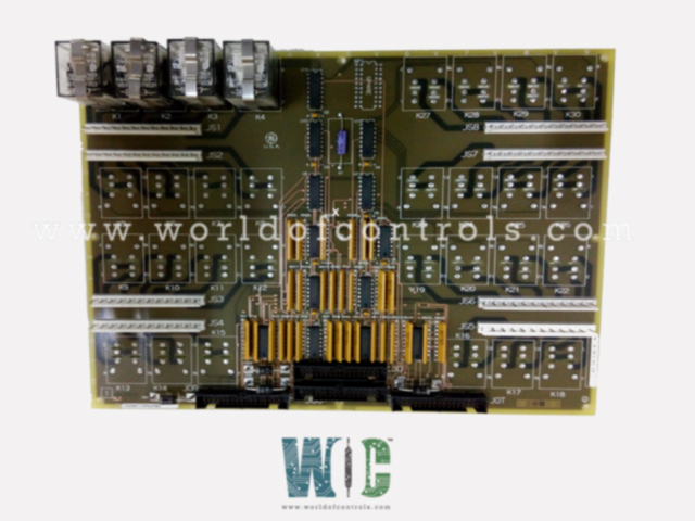
DS200TCRAG2ABC is a Relay Output Board developed by GE. It is a part of Mark V control system. The Relay Output Board (TCRA), located within the digital cores of the system, manages relay operations. Each board can contain up to 30 relays, identified as K1 through K30. There are two boards in each digital I/O core, providing redundancy and capacity. Notably, the board in location four of the Q11 core is an exception, containing only four relays. These specific relays are connected to the TCQE via the JO connector and are typically used to operate gas manifold blow-off valves in certain applications.
Features
- Full Complement Boards: All other boards, aside from the one in location four of Q11, have a full complement of 30 relays, offering extensive control capabilities.
- Solenoid Power Source Configuration: The first 18 relays on the board in location four of Q51 can be configured to provide a power source for operating solenoids. Similarly, the first 16 relays in location five of both the Q11 and Q51 cores can be configured this way. This configuration is achieved using hardware jumpers on the DTBC and DTBD terminal boards, allowing for flexible adaptation to specific operational requirements.
- Additional Contact Outputs: Two additional contact outputs, numbered 47 and 48, can be activated on the board in location five of either Q11 or Q51. These outputs can be wetted using power connectors J19 and J20, which supply 120/240 V AC power from the PD core to the DTBD board in one of the cores. These outputs are typically utilized for ignition transformers, demonstrating the board's ability to manage high-power applications.
- Signal Writing and Control: The signals to open or close the relays on the boards are sent by the boards located in the digital cores. For the board in location four of Q11, the control signals are sourced from the TCQE board in the R1 core. This specific routing ensures that the correct signals are delivered for relay operation.
- Restrictions: It's important to note that the first 18 solenoid outputs in Q21 cannot be configured as solenoid power sources. This restriction is a critical consideration during system setup and configuration.
Connectors
- JO Connector: The JO connector is responsible for writing signals to the board. In location five, it connects to the TCRA board for the Q11, Q21, and Q51 cores. In location four, it connects to the board for the Q21 and Q51 cores. It also writes signals from the TCQE board in the R1 core to the TCRA board in location four of the Q11 core, specifically to control the gas manifold blow-off valve.
- JS1 Connector: The JS1 connector connects relay outputs to the DTBC/D terminal board. It is used universally for all relevant connections between the TCRA and DTBC/D terminal boards.
- JS2 Connector: Similar to JS1, the JS2 connector links relay outputs to the DTBC/D terminal board. The board in Q11 does not use the JS2 connector to connect to the DTBC.
- JS3 Connector: The JS3 connector also connects relay outputs to the DTBC/D terminal board. The board in Q11 does not use the JS3 connector to connect to the DTBC.
- JS4 Connector: Like the previous connectors, the JS4 connector links relay outputs to the DTBC/D terminal board. The board in Q11 does not use the JS4 connector to connect to the DTBC.
- JS5 Connector: The JS5 connector is another relay output connector to the DTBC/D terminal board. The TCRA board in Q11 does not use the JS5 connector to connect to the DTBC.
The WOC team is always available to help you with your Mark V requirements. For more information, please contact WOC.
Frequently Asked Questions
What is DS200TCRAG2ABC?
It is a Relay Output Board developed by GE under the Mark V series.
How are the relays on the boards operated?
The relays on the boards are operated by signals originating from the CSP. These signals are transmitted to the STCA board over COREBUS.
What role does the STCA board play in relay operation?
The STCA boards receive signals from the CSP over COREBUS and interpret them. They then transmit these signals to the boards via the IONET communication protocol.
How do the boards contribute to relay operations?
The boards receive command signals from the STCA boards via the IONET. These command signals are written to the boards using the JO connector, which energizes the relays based on the received commands.
