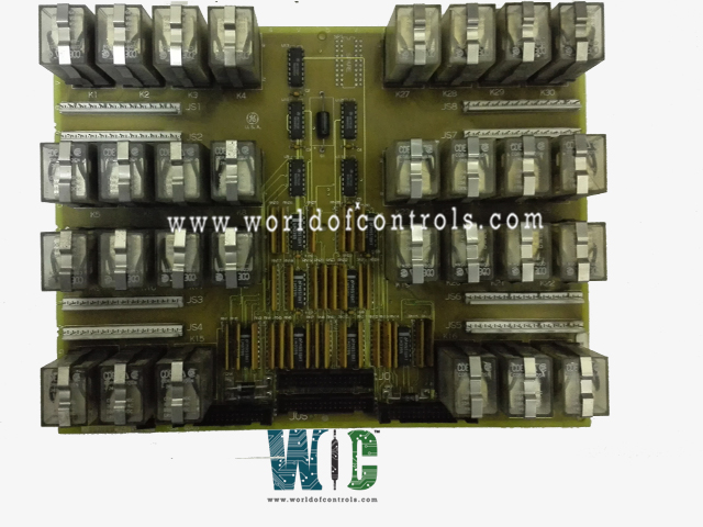
World Of Controls understands the criticality of your requirement and works towards reducing the lead time as much as possible.
DS200TCRAG1ABB - Relay Output Board is available in stock which ships the same day.
DS200TCRAG1ABB - Relay Output Board comes in UNUSED as well as REBUILT condition.
To avail our best deals for DS200TCRAG1ABB - Relay Output Board, contact us and we will get back to you within 24 hours.
SPECIFICATIONS:
Part Number: DS200TCRAG1ABB
Manufacturer: General Electric
Series: Mark V LM
Product Type: Relay Output Board
Location:
Power Handling: 335 V DC
Relay Switching Time: <10 ms
Input Voltage: 24V DC
Operating Temperature: 0°C to 60°C
Repair: 3-7 Days
Availability: In Stock
Country of Origin: United States
Manual: GEH-6421I
FUNCTIONAL DESCRIPTION:
DS200TCRAG1ABB is a Relay Output Board manufactured and designed by General Electric as part of the Mark V LM Series used in GE Speedtronic Gas Turbine Control Systems. The Relay Output Board (TCRA), located in the digital cores, contains up to 30 relays, K1 through K30. There are two of these boards in each digital IO core. The TCRA board in location four of the
TCRA CONNECTORS:
TCRA CONFIGURATION:
Hardware: The hardware configuration that powers the relays or converts them into solenoids is done at the terminal board level on the DTBC (Digital Terminal Board C) and DTBD (Digital Terminal Board D). These boards facilitate the connection and control of various components within the system. The DTBC and DTBD are designed to provide reliable communication between the control system and the actuators, ensuring seamless performance of the turbine control system. The configuration of the terminal boards involves setting up relay or solenoid control signals and their corresponding input/output connections. This setup allows the system to interface with external equipment, such as valves, switches, and sensors, by either energizing or de-energizing relays or solenoids based on the control logic. The configuration process can include:
TCRA CONTACT OUTPUT CIRCUITS:
The relays on the TCRA boards are operated by signals originating from the CSP (Control Signal Processor), which sends these signals to the STCA (Signal Transmission Control Actuation) board over the COREBUS. The COREBUS serves as the communication medium for transmitting control signals between the CSP and the STCA board, ensuring synchronized data exchange and control actions.
Once the STCA board receives the control signals, it processes them and forwards the appropriate commands to the TCDA (Turbine Control Digital Actuation) boards through the IONET. The IONET is a dedicated communication network that allows for high-speed, real-time data transmission across multiple control and monitoring units within the turbine control system.
The TCDA boards then interpret these signals and send the appropriate command signals to energize or de-energize the relays. This action is achieved through the JO (Junction Output) connector, which is responsible for delivering the necessary current and voltage to the relay coils. The relays themselves control the actuation of various field devices, such as valves, pumps, and switches, by either opening or closing their contacts.
WOC has the largest stock of OEM Replacement Parts for GE Speedtronic Gas Turbine Control Systems. We can also repair your faulty boards and supply unused and rebuilt boards backed up with a warranty. Our team of experts is available around the clock to support your OEM needs. Our team of experts at WOC is happy to assist you with any of your automation requirements. For pricing and availability on parts and repairs, kindly contact our team by phone or email.
How does COREBUS communicate between the CSP and STCA boards?
COREBUS is the communication network that connects the Control Signal Processor (CSP) to the Signal Transmission Control Actuation (STCA) board. It transmits control signals in real time to ensure synchronized control actions between the system components.
What is the function of the JO connector?
The JO (Junction Output) connector is used to send the command signals from the TCDA board to energize or de-energize the relays. These signals control the opening and closing of relay contacts, which in turn manage the activation or deactivation of field devices such as valves, pumps, and switches.
What devices are controlled by the relays in the TCRA system?
The relays in the TCRA system control various field devices, including valves, switches, pumps, and other critical components within the turbine control system. These devices are activated or deactivated by the relays' open/close contacts.