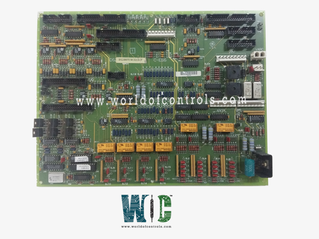
World Of Controls understands the criticality of your requirement and works towards reducing the lead time as much as possible.
DS200TCQCG1BKG - Analog IO Expander Board is available in stock which ships the same day.
DS200TCQCG1BKG - Analog IO Expander Board comes in UNUSED as well as REBUILT condition.
To avail our best deals for DS200TCQCG1BKG - Analog IO Expander Board, contact us and we will get back to you within 24 hours.
SPECIFICATIONS:
Part Number: DS200TCQCG1BKG
Manufacturer: General Electric
Series: LM2500
Product Type: Analog IO Expander Board
Number of Channels: 16 channels.
Input Voltage Range: 0 to 5V
Number of Channels: 2 channels for DAC
Power Requirements: +5 V dc
Repair: 3-7 Day
Availability: In Stock
Country of Origin: United States
Manual: GEH-6153
FUNCTIONAL DESCRIPTION:
DS200TCQCG1BKG is an Analog IO Expander Board manufactured and designed by General Electric as part of the LM2500 Series used in GE Aeroderivative Gas Turbine Control Systems. The Analog IO Expander board (TCQC) provides scaling and conditioning for additional analog signals read from the terminal boards of the I/O cores. The TCQC board provides LVDT and LVDR excitation. The IONET termination for
TCQC PULSE RATE INPUT CIRCUIT:
The high-pressure shaft pulse rate signals are read from the TCQE board via the JJ connector. The TCQE board signals originate on the PTBA board in the
TCQC CONFIGURATION:
Hardware: The first 16 hardware jumpers on the TCQC board configure the output current range for the servo outputs. The even-numbered jumpers select the feedback scaling, while the odd-numbered jumpers select the source output resistance. Hardware jumpers 25 through 36 are for added feedback scaling options for servos one through four, giving them a maximum current range of +/- 240 mA. BJ17 sets the RS232 port for card tests. BJ21 is the stall timer enabled. BJ22 is the oscillator enabled for factory tests. BJ23 and BJ24 are not used. BJ18 and BJ20 limit the P15 and N15 supply to the proximity transducers. Hardware jumpers JP38 and JP39 set the magnetic pickup gain for liquid fuel flow signals in some applications. Refer to Appendix A and the paragraphs below for information on the hardware jumper settings for this board.
WOC has the largest stock of OEM replacement parts for GE Aeroderivative Gas Turbine Control Systems. We can also repair your faulty boards and supply unused and rebuilt boards backed up with a warranty. Our team of experts is available round the clock to support your OEM needs. Our team of experts at WOC is happy to assist you with any of your automation requirements. For pricing and availability on parts and repairs, kindly contact our team by phone or email.
What is an Analog IO Expander Board?
An Analog IO Expander Board is a device that extends the input/output capabilities of a microcontroller or digital system, specifically for handling analog signals. It typically provides additional analog input and output channels beyond what the microcontroller alone can support.
How does an Analog IO Expander Board work?
The board interfaces with a microcontroller or digital system using communication protocols like I2C, SPI, or UART. It translates digital signals from the microcontroller into analog signals for output and converts external analog signals into digital data for the microcontroller to process.
What are the common applications of Analog IO Expander Boards?
These boards are used in applications where the microcontroller has limited analog input/output capabilities. Common applications include sensor interfacing, industrial automation, data acquisition systems, and control systems.