SPECIFICATIONS
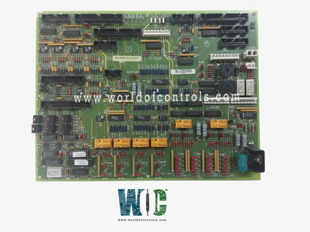
Part No.: DS200TCQCG1BGE
Manufacturer: General Electric
Country of Manufacture: United States of America (USA)
Product Type: Analog IO Expander Board
Availability: In Stock
Series: Mark V
Functional Description
DS200TCQCG1BGE is an Analog IO Expander Board developed by GE. It is a part of the Mark V control system. The Analog IO Expander board provides scaling and conditioning for additional analog signals sourced from the terminal boards of the I/O cores. This board is integral for ensuring accurate and reliable data acquisition and processing within the system architecture.
Features
- LVDT and LVDR Excitation: It provides excitation for LVDT (Linear Variable Differential Transformer) and LVDR (Linear Variable Differential Resistor) signals, ensuring precise measurement and feedback capabilities.
- IONET Termination: In the R1 core, the board terminates the IONET for Q11 and P1. If the optional 21 is installed, this termination function shifts to the board in R2, optimizing network connectivity and signal integrity.
- Megawatt Transducer Signal: The board scales and conditions the mA input for megawatt transducer signals, preparing them for transmission to the STCA board via the 19PL connector. This process ensures accurate measurement and monitoring of power output.
- Pulse Rate Inputs: Pulse rate inputs undergo scaling and conditioning on the board, making them suitable for integration into the system's operational framework.
High-Pressure Shaft Speed and Liquid Fuel Flow Signals: In most applications, signals such as high-pressure shaft speeds and occasionally liquid fuel flows are scaled on the TCQC board. These processed signals are then transmitted to the board via the JE connector in the R1 core, facilitating comprehensive monitoring and control capabilities.
- Communication with STCA Board: The board communicates generator and line signals with the STCA board via the JE connector, ensuring seamless integration and synchronization of critical operational parameters.
- Optimizing System Performance: By providing precise scaling and conditioning of analog signals, the board enhances the overall performance and reliability of the system. It facilitates accurate data acquisition and transmission, essential for maintaining operational efficiency and safety across various operational scenarios.
Pulse Rate Input Circuit
- The pulse rate input circuit is essential for accurately monitoring and processing high-pressure shaft pulse rate signals within the system. These signals, originating from the PTBA board located in the P1 core, are crucial for monitoring the rotational speed of high-pressure shafts, ensuring operational safety and efficiency.
- High-pressure shaft pulse rate signals are first read from the board via the JJ connector, establishing a direct pathway for data transmission from the PTBA board. This connection ensures that real-time pulse rate data is effectively relayed to subsequent processing stages within the system.
- Once received, these signals are transmitted to the board through the JE connector. Here, they undergo scaling and conditioning processes to ensure accuracy and reliability. This step is crucial for converting raw pulse rate data into usable information that supports precise operational monitoring and control.
- The pulse rate input circuit also accommodates inputs from various sensor types, including magnetic speed sensors and TTL type sensors. These sensors, typically connected to the TBQB terminal board, pass their pulse rate inputs through the board via the JH connector. This integration broadens the scope of monitored parameters, enhancing the system's capability to respond to different operational conditions.
- To maintain signal integrity and prevent operational conflicts, it's essential to manage the configuration of terminal boards effectively. Signals landed on the PTBA terminal board should not overlap with those on the QTBA terminal board to avoid data redundancy and ensure consistent data acquisition and processing.
- By leveraging dedicated connectors and boards, such as the JGG connector for magnetic pickup pulse rate signals from the QTBA board, the system optimizes its ability to handle diverse input sources. This approach enhances operational flexibility and ensures robust performance across various operational scenarios.
The WOC team is always available to help you with your Mark V requirements. For more information, please contact WOC.
Frequently Asked Questions
What is DS200TCQCG1BGE?
It is an Analog IO Expander Board developed by GE under the Mark V series.
How are the pulse rate signals processed within the system?
Upon receiving the signals, the TCQE board transmits them to the TCQA board via the JE connector. Here, the signals undergo scaling and conditioning to ensure accuracy and reliability before being further integrated into the system.
What other types of sensors contribute to the pulse rate input circuit?
The circuit accommodates inputs from various sensors, including magnetic speed sensors and TTL type sensors connected to the TBQB terminal board. These sensors pass their pulse rate inputs through the TCQC board via the JH connector, expanding the range of monitored parameters.
How does the system manage signal integrity to prevent conflicts?
To maintain signal integrity, it's crucial to ensure that signals landed on the PTBA terminal board do not overlap with those on the QTBA terminal board. This prevents data redundancy and ensures consistent data acquisition and processing.
