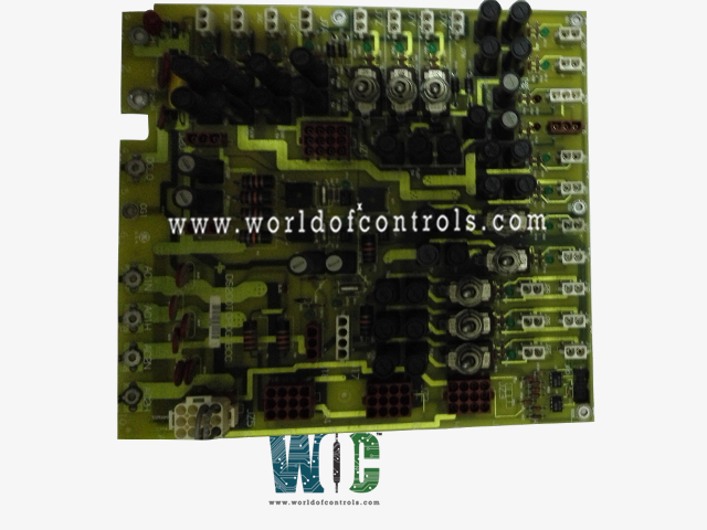
World Of Controls understands the criticality of your requirement and works towards reducing the lead time as much as possible.
DS200TCPDG1BCC - Power Distribution Module is available in stock which ships the same day.
DS200TCPDG1BCC - Power Distribution Module comes in UNUSED as well as REBUILT condition.
To avail our best deals for DS200TCPDG1BCC - Power Distribution Module, contact us and we will get back to you within 24 hours.
SPECIFICATIONS:
Part Number: DS200TCPDG1BCC
Manufacturer: General Electric
Series: Mark V LM
Board rating: 125 V dc
Product Type: Power Distribution Module
Impedance to the ground: 75 Ohm
Power Requirements: +5 V dc, 6 A
Operating temperature: -30 to +65°C
Size: 30.48cm High x 21.33cm
Mounting: 4 mounting Holes
Repair: 3-7 Day
Availability: In Stock
Country of Origin: United States
Manual: GEH-6353B
FUNCTIONAL DESCRIPTION:
DS200TCPDG1BCC is a Power Distribution Module manufactured and designed by General Electric as part of the Mark V LM Series used in GE Linear Microprocessor Control Systems. The Power Distribution Module (TCPD), located in the
TCPD CONNECTORS:
J7X – Distributes the 125 V dc power to the TCEA board in location one ,
J7Y – Distributes the 125 V dc power to the TCEA board in location three,
J7Z – Distributes the 125 V dc power to the TCEA board in location five,
J8A – Distributes the 125 V dc power to the DTBC board in the
J8B – Distributes the 125 V dc power to the DTBD board in the
J8C – Distributes the 125 V dc power to the DTBC board in the
J8D – Distributes the 125 V dc power to the DTBD board in the
J12A – Distributes the 125 V dc power to the DTBA board in the
J12B – Distributes the 125 V dc power to the DTBA board in the
JPD – Distributes 5 V dc power to the CTBA board in the
JZ1 – Connection for the TCEA boards and contact input power to drop across the external resistors.
JZ2 – Incoming AC from the TB1 terminal board connected through JZ2 to the DACA, (AC to DC converter), via the JZ connector in the DACA box. Used for AC to DC conversion.
JZ3 – Alternate for JZ2 if the reduced voltage is needed for a special contact output circuit (contact output #18 on the DTBC board of the
JZ4 – Auxiliary AC source connection point for applications that require an isolated input for an uninterruptible power source connection(s) and/or switched backup power source. Typically used for a Black Start Inverter.
JZ5 – Standard AC power source connection for the ignition transformers.
TCPD CONFIGURATION:
HARDWARE: The BJS hardware jumper is supplied for isolation of the ground reference on systems with an external reference. When the jumper is in, the ground reference is provided for the external reference systems. Refer to Appendix A and the hardware jumper screen on the operator interface for information on the hardware jumper settings for this board.
TCPD SWITCHES:
The TCPD board has several switches associated with it. Each switch toggles on and off the power for the particular core or board associated with it.
SW1 – Toggles power in the
SW2 – Toggles power in the
SW3 – Toggles power in the
SW4 – Toggles power in the
SW5 – Toggles power in the
SW6 – Toggles power on
SW7 – Toggles power on
SW8 – Toggles power on
TCPD POWER:
External 115/230 V ac power is brought in via the TB1 terminal board mounted on the
WOC has the largest stock of OEM replacement parts for GE Linear Microprocessor Control Systems. We can also repair your faulty boards and supply unused and rebuilt boards backed up with a warranty. Our team of experts is available round the clock to support your OEM needs. Our team of experts at WOC is happy to assist you with any of your automation requirements. For pricing and availability on parts and repairs, kindly contact our team by phone or email.
What is a Power Distribution Module (PDM) in a linear microprocessor?
A Power Distribution Module (PDM) in a linear microprocessor is a component that manages and distributes power efficiently to various subsystems within the microprocessor, ensuring stable and reliable operation.
How does a PDM improve the performance of a linear microprocessor?
A PDM improves performance by providing consistent and regulated power, reducing the chances of power fluctuations, and ensuring that each subsystem receives the appropriate voltage and current levels.
What are the key features of a Power Distribution Module?
Key features include overcurrent protection, voltage regulation, thermal management, and fault detection. These features help maintain the integrity and reliability of the microprocessor.