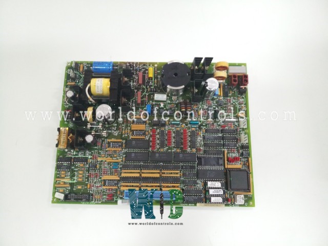
World Of Controls understands the criticality of your requirement and works towards reducing the lead time as much as possible.
DS200TCEAG2BME - Emergency Overspeed Board is available in stock which ships the same day.
DS200TCEAG2BME - Emergency Overspeed Board comes in UNUSED as well as REBUILT condition.
To avail our best deals for DS200TCEAG2BME - Emergency Overspeed Board, contact us and we will get back to you within 24 hours.
SPECIFICATIONS:
Part Number: DS200TCEAG2BME
Manufacturer: General Electric
Series: Mark V LM
Board rating: 125 V dc
Product Type: Emergency Overspeed Board
Impedance to the ground: 75 Ohm
Power Requirements: +5 V dc, 6 A
Operating temperature: -30 to +65�C
Size: 30.48cm High x 21.33cm
Mounting: 4 mounting Holes
Repair: 3-7 Day
Availability: In Stock
Country of Origin: United States
Manual: GEH-6721D
FUNCTIONAL DESCRIPTION:
DS200TCEAG2BME is an Emergency Overspeed Board manufactured and designed by General Electric as part of the Mark V LM Series used in GE Speedtronic Control Systems. The Emergency Overspeed Board (TCEA), located in the Protective Core
The I/O Engine in the
TCEA CONNECTORS:
JK - Carries the signals to the TCEA board from the TCEB board in location two of the
JL - Carries the trip signals to the Turbine Trip Board (TCTG) in location four of the
JW - Carries the 335 V dc for the flame detectors to the TCEB board. JW connects to the JWX/Y/Z connectors on the TCEB board.
JX1 - Daisy chained IONET connectors. JX1 on
JX2 - Daisy chained IONET connectors. JX2 on
TCEA CONFIGURATION:
Hardware: The TCEA board is hardware jumpers J1 and J31 are used for factory tests. J2 and J3 are used for IONET termination resistors. Hardware jumpers J4, J5, and J6 are used to set up the IONET address for each TCEA board. Overspeed trip frequency settings are confirmed using J12 through J21 for the high-pressure shaft J8 through J11 and J22 through 27 for the low-pressure shaft. The actual configuration is done through the I/O configuration software. J28 and J29 hardware jumpers cause
Software: The IO Configuration Editor is used to set the base speed and overspeed values for both the high and low-pressure shafts and calculate the hardware jumper settings for trip frequency. The pulse rate information from the Ultra Violet (UV) flame detectors is selected and the auto-synchronization permissive values are chosen in the IO Configuration Editor as described below.
WOC has the largest stock of OEM replacement parts for GE Speedtronic Control Systems. We can also repair your faulty boards and supply unused and rebuilt boards backed up with a warranty. Our team of experts is available round the clock to support your OEM needs. Our team of experts at WOC is happy to assist you with any of your automation requirements. For pricing and availability on parts and repairs, kindly contact our team by phone or email.
How does the Emergency Overspeed Board function in the Speedtronic Mark V LM system?
The board continuously monitors the speed of the gas turbine. If the turbine exceeds a predetermined speed limit, the board activates protective measures such as shutting down the turbine, triggering alarms or initiating emergency braking to prevent damage or accidents.
Why is the Emergency Overspeed Board crucial for gas turbine safety?
Gas turbines operate at high speeds and are susceptible to severe damage if they overspeed. The Emergency Overspeed Board provides a vital safety mechanism to prevent overspeed conditions, protecting the turbine and ensuring the safety of personnel and equipment.
Can the speed limit settings on the Emergency Overspeed Board be adjusted?
Yes, the speed limit settings can be configured to meet the specific operational and safety requirements of the gas turbine. This ensures optimal performance and protection based on the turbine's characteristics and operational parameters.