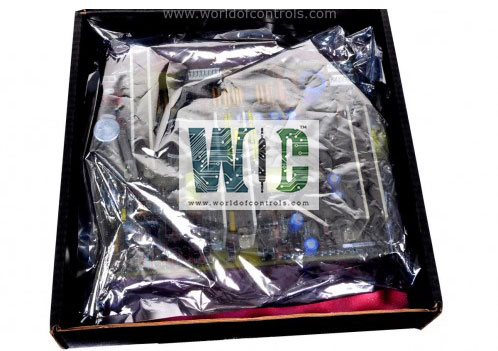
SPECIFICATIONS
Part No.: DS200TCEAG1AHB
Manufacturer: General Electric
Country of Manufacture: United States of America (USA)
Product Type: Emergency Overspeed Board
Availability: In Stock
Series: Mark V
Functional Description
DS200TCEAG1AHB is an emergency overspeed board developed by GE. It is a part of the Mark V control system. The Emergency Overspeed Board is a component located in Protective Core P1. It is commonly referred to as the protective processor and is essential for high-speed protection circuitry.
Features
- Location and Identification: The board is situated in Protective Core P1. There are three boards within this core, designated as X, Y, and Z processors. These processors work together to handle critical protection functions.
- Signal Processing: Each board receives signals related to high and low shaft speed, flame detection, and automatic synchronization. These signals are crucial for monitoring and protecting the system.
- Signal Scaling and Conditioning: The boards scale and condition the incoming signals to ensure accurate and reliable data processing.
- Data Transmission via IONET: The processed signals are transmitted over the IONET network to the STCA board located in the R1 core. The transmission is handled through the JX1 connector on the board in location one (X processor). The boards in locations three (Y processor) and five (Z processor) use the JX1 and JX2 connections to transfer their information via the X processor.
- Median Select and Data Usage: The I/O Engine in the R1 core uses the data from the three boards and performs a median select on the three values. This process ensures that the most accurate and reliable data is used. The results are then transferred across the COREBUS to the Control Engine.
- Emergency Trip Signals: The boards send emergency trip signals to the Turbine Trip Board (TCTG). Each board sends a trip signal to different relays on the TCTG board. These three relays perform a two-out-of-three voting mechanism (relay driver level voting) to determine whether the TCTG board should trip the unit.
- Power Supply and Diagnostics: Each board has its own power supply and power supply diagnostics, ensuring reliable operation and easy troubleshooting.
Connectors
- J7 Connector: Distributes power from the PD core to each board. This connector ensures that each board receives the necessary power supply to operate effectively.
- JK Connector: Carries signals from the TCEB board located in position two of the P1 core to the TCEA board. The JK connector connects to either JKX, JKY, or JKZ connectors on the TCEB board. Each board (X, Y, Z processors) connects to a specific JK connector (JKX for X, JKY for Y, JKZ for Z), facilitating the transfer of essential signals from the TCEB to the TCEA boards.
- JL Connector: Carries trip signals to the Turbine Trip Board (TCTG) located in position four of the P1 core. Each connects to a different connection on the TCTG board via the
- JL connector. Specifically, JL on X connects to JLX, JL on Y connects to JLY, and JL on Z connects to JLZ, enabling each board to send trip signals independently to the TCTG board.
- JW Connector: Carries the 335 V DC for the flame detectors to the TCEB board. The JW connector connects to the JWX, JWY, or JWZ connectors on the TCEB board. Similar to the JK connector, each board (X, Y, Z processors) connects to a specific JW connector (JWX for X, JWY for Y, JWZ for Z), ensuring proper power supply for the flame detectors.
- JX1 Connector: Daisy-chained IONET connectors used for signal transmission. JX1 on X connects directly to the JX connector on the TCQC board in the R1 core. This connection facilitates the reading and writing of signals from the P1 core and Q11 core to the I/O Engine in R1. JX1 on Y connects to the JX2 socket on X, and JX1 on Z connects to the JX2 socket on Y, forming a daisy chain that allows signals to be transmitted from board to board until they reach the TCQC board in the R1 core.
- JX2 Connector: Another set of daisy-chained IONET connectors. JX2 on X connects to the JX1 connector on Y, JX2 on Y connects to the JX1 connector on Z, and JX2 on Z connects to the TCDA board in the Q11 core. This daisy chain configuration ensures continuous transmission of digital signals up the IONET to the R1 core.
The WOC team is always available to help you with your Mark V requirements. For more information, please contact WOC.
Frequently Asked Questions
What is DS200TCEAG1AHB?
It is an emergency overspeed board developed by GE under the Mark V series.
What is the role of the JW connector?
The JW connector on the TCA board carries the 335 V DC power supply for the flame detectors to the TCEB board. Each board (X, Y, Z processors) connects to a specific JW connector (JWX for X, JWY for Y, JWZ for Z) on the TCEB board, ensuring proper power supply for the flame detectors.
How do the JX1 and JX2 connectors function?
The JX1 and JX2 connectors are daisy-chained IONET connectors. JX1 on X connects directly to the JX connector on the TCQC board in the R1 core, facilitating signal transmission from the P1 core and Q11 core to the I/O Engine in R1. JX1 on Y connects to JX2 on X, and JX1 on Z connects to JX2 on Y, forming a daisy chain that allows continuous transmission of signals until they reach the TCQC board in the R1 core.
Can JX1 and JX2 connectors be used interchangeably?
No, JX1 and JX2 connectors have specific roles in the daisy chain configuration. JX1 primarily connects downstream to the next board in the chain, while JX2 connects upstream to the previous board in the chain. This configuration ensures proper signal transmission along the IONET network.
