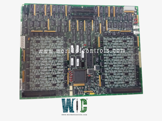
World Of Controls understands the criticality of your requirement and works towards reducing the lead time as much as possible.
DS200TCDAH1BHF - Digital I/O Board is available in stock which ships the same day.
DS200TCDAH1BHF - Digital I/O Board comes in UNUSED as well as REBUILT condition.
To avail our best deals for DS200TCDAH1BHF - Digital I/O Board, contact us and we will get back to you within 24 hours.
SPECIFICATIONS:
Part Number: DS200TCDAH1BHF
Manufacturer: General Electric
Series: Mark V LM
Product Type: Digital I/O Board
Power Requirements: +5 V dc, 6 A
Number of relay channels: 32
Power supply voltage: 28 V dc
Mounting: DIN-rail mounting
Technology: Surface mount
Operating temperature: -30 to +65°C
Size: 15.9 cm high x 17.8 cm
Repair: 3-7 Day
Availability: In Stock
Country of Origin: United States
Manual: GEI-100182B
FUNCTIONAL DESCRIPTION:
DS200TCDAH1BHF is a Digital I/O Board manufactured and designed by General Electric as part of the Mark V LM Series used in GE Speedtronic Control Systems. The Digital I/O Board (TCDA) resides within the digital I/O cores
TCDA CONFIGURATION:
HARDWARE: The TCDA board includes eight hardware jumpers, each serving specific functions. J1 and J8 are reserved for factory testing, while J2 and J3 manage IONET termination resistors. Jumpers J4, J5, and J6 set the board's IONET ID, and J7 activates the stall timer. For detailed settings, refer to Appendix A and the hardware jumper screen in the operator interface.
TCDA CONNECTORS:
WOC has the largest stock of GE Speedtronic control system replacement parts. We can also repair your faulty boards and supply unused and rebuilt boards backed up with a warranty. Our team of experts is available round the clock to support your OEM needs. Our team of experts at WOC is happy to assist you with any of your automation requirements. For pricing and availability on parts and repairs, kindly contact our team by phone or email.
How is the IONET ID assigned to the TCDA board?
The IONET ID is set using the hardware jumpers J4, J5, and J6. Each combination corresponds to a unique ID that allows the board to communicate properly within the system.
What is the purpose of the stall timer enabled by J7?
The stall timer monitors the system's operation and triggers safety mechanisms if abnormal conditions, such as unresponsive components, are detected.
How are input signals validated by the TCDA board?
The board uses internal diagnostics to validate digital inputs, ensuring signal integrity and proper operation before relaying them to other components.