SPECIFICATIONS
Part No.: DS200TCDAH1BCD
Manufacturer: General Electric
Country of Manufacture: United States of America (USA)
Product Type: Digital I/O Board
Availability: In Stock
Series: Mark V
Functional Description
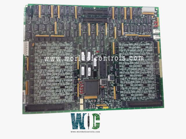
DS200TCDAH1BCD is a digital I/O board developed by GE. It is a part of the Mark V control system. The Digital I/O Board is a component located in the digital I/O cores Q11 and Q51. Its primary function is to process digital contact input and output signals within the system.
Features
- The board is situated in the digital I/O cores labeled Q11 and Q51. This strategic placement allows it to efficiently manage and process digital signals from various sources.
- The board handles digital contact input signals received from the DTBA and DTBB terminal boards. These input signals are crucial for the system to monitor and respond to various digital events and states.
- The board also manages contact output signals, which include relay and solenoid signals. These signals are sourced from two TCRA boards, allowing the system to control and actuate various external devices and components.
- Signals processed by the board are transmitted over the IONET network. This ensures reliable and efficient communication within the system, facilitating seamless data transfer and control.
- The board communicates with the TCQC board located in R1 and the CTBA terminal board in R5. This interface is essential for coordinating signal processing and control tasks across different parts of the system.
Connectors
- JP Connector: Distributes power from the TCPS board located in the R1 and R5 cores to the Q11 and Q51 cores, respectively. This ensures that the board receives the necessary power to operate effectively.
- JQ Connector: Connects to the JQR socket on the DTBA board. This connection carries the contact input signals from the DTBA board to the board, allowing the system to receive and process input signals.
- JR Connector: Connects to the JRR socket on the DTBB board. Similar to the JQ connector, this connection carries the contact input signals from the DTBB board to the board, ensuring that all input signals are accurately transmitted and processed.
- JO1 Connector: Writes the contact output (relay/solenoid) signals to the TCRA board located in position four. This connector is generally not used in the Q11 core, indicating that its primary function is specific to certain configurations or locations.
- JO2 Connector: Writes the contact output (relay/solenoid) signals to the TCRA board located in position five. This connector is commonly used in both the Q11 core and the Q51 core, making it a critical component for output signal transmission.
- JX1 Connector: A shielded twisted pair for the IONET signals. The board in the Q11 core writes signals to the JX2 connection on the TCEA board in position five of the P1 core. The board in the Q51 core writes signals to the JX connection on the CTBA terminal board in the R5 core. This connector ensures reliable communication and signal transmission over the IONET network.
- JX2 Connector: Used for the same function as JX1. Either JX1 or JX2 can be used interchangeably, providing flexibility in system configuration and signal routing.
The WOC team is always available to help you with your Mark V requirements. For more information, please contact WOC.
Frequently Asked Questions
What is DS200TCDAH1BCD?
It is a digital I/O board developed by GE under the Mark V series.
How does the JQ connector interact with the board?
The JQ connector connects to the JQR socket on the board, carrying the contact input signals from the DTBA board to the board. This allows the system to receive and process these input signals accurately.
What is the purpose of the JR connector?
The JR connector connects to the JRR socket on the board and carries the contact input signals from the board to the board, ensuring that all input signals are accurately transmitted and processed.
Why is the JO1 connector generally not used in the Q11 core?
The JO1 connector writes the contact output signals to the TCRA board in position four. It is generally not used in the Q11 core, indicating that its use is specific to certain configurations or locations.
