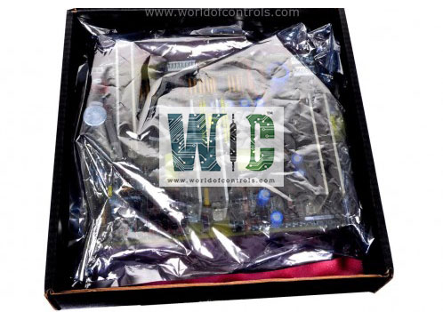
SPECIFICATIONS
Part No.: DS200TCCBG7B
Manufacturer: General Electric
Series: Mark V
Product type: Common Extended Analog IO Board
Repair: 3-5 Days
Availability: In Stock
Country of Manufacture: United States (USA)
Functional Description
DS200TCCBG7B is a Common Extended Analog IO Board developed by GE. It is a part of Mark V LM gas turbine control system. It provides essential scaling and conditioning for additional analog I/O signals, which are critical for monitoring various parameters in the turbine's operation. These signals include inputs such as 4-20 mA, 0-1 mA, RTDs (Resistance Temperature Detectors), generator and bus voltage, and line current inputs. The TCCB processes these signals, ensuring they are properly scaled and conditioned before being sent to other components of the control system.
Features
- 4-20 mA/0.1 mA Input Signals: These signals are read from the TBCB terminal board via the JHH connector.
- RTD Input Signals: The board receives these signals from the TBCB terminal board through the JII connector.
- Generator and Bus Voltage Inputs: These signals are scaled and conditioned on the board and are transferred via the JMP connector from the TCEB board in the P1 core.
- Line Current Inputs (PT and CT signals): These are scaled and conditioned for power system monitoring.
Connectors and Their Functions
- 2PL: Distributes power from the TCPS board in the R5 core to the TCCB.
- 3PL: Acts as the data bus between the STCA, TCCA, and TCCB boards, transmitting conditioned signals to the COREBUS.
- JHH: Carries the 4-20 mA/0.1 mA input signals from the TBCB terminal board.
- JII: Carries the RTD input signals from the TBCB terminal board.
- JMP: Carries the PT and CT signals (voltage and current transformer inputs) from the TCEB board in the P1 core.
- JKK, JTEST, TCQPL: These connectors are typically not used.
Hardware Configuration
- The board has several hardware jumpers (e.g., J1, J2, J3, J4, J5) that are used for functions like generator and bus voltage monitoring and line current monitoring.
- Jumper J14 is used for connecting the RS232 serial port to DCOM, while J15 and J16 are used for testing purposes.
- The hardware jumper settings can be reviewed through the operator interface or by referencing the documentation in Appendix A for specific configurations.
Software Configuration
- The I/O configuration constants for RTDs, mA inputs, generator and bus voltage, and line current are configured through the I/O Configuration Editor located in the HMI (Human-Machine Interface). This allows the system to accurately read and process the various signals handled by the TCCB board.
4-20 mA Input Circuit
- These signals are read from the TBCB terminal board via the JHH connector.
- The transducer current is dropped across a burden resistor, and the resulting voltage drop is read by the board.
- The TCCB then transmits the scaled signal to the I/O Engine via the 3PL connector.
RTD Circuit
- The current sent through the RTD changes its resistance based on temperature.
- This change in resistance results in a change in the voltage across the RTD, which is then measured, scaled, and conditioned by the TCCB.
- The RTD signals are read from the TBCB terminal board via the JII and JDD connectors and are then sent to the I/O Engine for further processing.
Generator/Bus Voltage and Current Input Circuits
- The voltage signals from the generator and bus, along with the current signals from the line, are scaled and conditioned on the board.
- These signals are used for power system monitoring, helping to define phase currents and voltages, and calculate the generator megawatt output, power factor, and VARs (volt-amperes reactive).
- These signals are received from the PTBA terminal board, scaled on the TCEB board, and transmitted to the board via the JMP connector.
World of Controls has the most comprehensive collection of GE Mark V components. Please contact WOC as soon as possible if you require any extra information.
Frequently Asked Questions
What is DS200TCCBG7B?
It is a Common Extended Analog IO Board developed by GE.
What role do hardware jumpers play in the board?
The hardware jumpers (e.g., J1, J2, J3, J4, J5) on the board are used for configuring specific monitoring functions such as generator and bus voltage and line current. Other jumpers (e.g., J14) are used to connect serial ports or for testing purposes.
What is the purpose of the 4-20 mA input circuit?
The 4-20 mA input circuit is used for reading signals from transducers (e.g., pressure, flow, or temperature sensors). The current is dropped across a burden resistor, and the resulting voltage drop is read by the board and transmitted to the I/O Engine.
