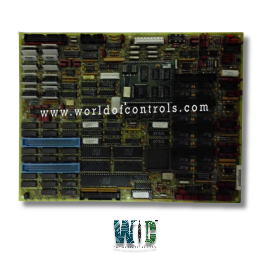
World Of Controls understands the criticality of your requirement and works towards reducing the lead time as much as possible.
DS200TCCAG1D - Common Analog I/O Board is available in stock which ships the same day.
DS200TCCAG1D - Common Analog I/O Board comes in UNUSED as well as REBUILT condition.
To avail our best deals for DS200TCCAG1D - Common Analog I/O Board, contact us and we will get back to you within 24 hours.
Part No.: DS200TCCAG1DAA
Manufacturer: General Electric
Country of Manufacture: United States of America (USA)
Temperature Operating: -30 to 65oC
Product Type: Analog I/O Board
Availability: In Stock
Series: Mark V
DS200TCCAG1DAA is an Analog I/O Board developed by GE. It is a part of Mark V control system. This board is responsible for scaling and conditioning various types of analog signals from multiple terminal boards, including the CTBA, TBQA, and TBCA terminal boards located in the R5 core of the control system.
These conditioned signals are then written to the STCA board through the 3PL connector.
The configuration of input and output constants for different signal types (e.g., thermocouples, RTDs, mA inputs, shaft voltage, and current) is managed through the I/O Configuration Editor, which is located on the Human-Machine Interface (HMI). This editor allows operators to enter the appropriate values to configure the system according to the specific needs of the application.
The WOC team is always available to help you with your Mark V requirements. For more information, please contact WOC.
What is DS200TCCAG1DAA?
It is an Analog I/O Board developed by GE under the Mark V series.
What software is used to configure the board?
The board is configured using the I/O Configuration Editor, which is accessible via the Human-Machine Interface (HMI), where operators can input and modify the necessary configuration values.
What is the function of the 3PL connector?
The 3PL connector serves as the data bus between the STCA, TCCA, and TCCB boards, facilitating the transfer of conditioned signals to the COREBUS.