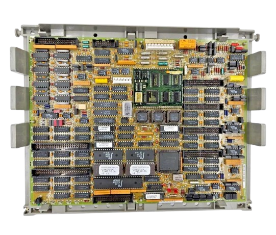
World Of Controls understands the criticality of your requirement and works towards reducing the lead time as much as possible.
DS200TCCAG1AJB - Common Analog I/O Board is available in stock which ships the same day.
DS200TCCAG1AJB - Common Analog I/O Board comes in UNUSED as well as REBUILT condition.
To avail our best deals for DS200TCCAG1AJB - Common Analog I/O Board, contact us and we will get back to you within 24 hours.
SPECIFICATIONS:
Part Number: DS200TCCAG1AJB
Manufacturer: General Electric
Series: Mark V
Product Type: Terminal Board
Input Channels: 8 Analog Inputs
Input Resolution: 12-bit / 16-bit
Output Type: Voltage (0-10V, ±10V)
Output Resolution: 12-bit / 16-bit
Input Type: Voltage (0-10V, ±10V)
Communication Protocol: RS-485
Power Supply: 24V DC ±10%, < 5W
Isolation: 1500V
Mounting Options: DIN Rail
Operating Temperature: -20°C to 70°C
Country/Region of Manufacture: United States
Availability: In Stock
FUNCTIONAL DESCRIPTION:
DS200TCCAG1AJB is a Common Analog I/O Board manufactured and designed by General Electric as part of the Mark V Series used in gas turbine control systems. The Common Analog I/O Board (TCCA) is an integral component of the turbine control system, located within the
The types of signals handled by the TCCA board include 4-20 mA analog inputs and outputs, which are widely used in industrial control systems for transmitting process variables over long distances with high noise immunity. Additionally, the board supports RTD (Resistance Temperature Detector) inputs, enabling precise and reliable temperature monitoring critical for turbine operation and safety.
The TCCA also processes thermocouple inputs, which are commonly used for high-temperature measurement in turbine applications. Moreover, it handles shaft voltage and shaft current inputs, which are essential for monitoring electrical conditions on the turbine shaft — helping to detect issues such as insulation breakdown or grounding problems that could impact operational efficiency and equipment longevity.
Once all signals are properly scaled and conditioned, the TCCA board transmits them to the STCA board via the 3PL connector, a ribbon cable that ensures fast and organized signal routing. This connection allows for the smooth integration of analog data into the turbine's control logic, contributing to effective monitoring, diagnostics, and control operations.
TCCA CONNECTORS:
TCCA CONFIGURATION:
Hardware: There are three hardware jumpers - J1, JP2, and JP3 on the TCCA board. J1 is used to enable/disable the serial RS232 port. JP2 is used to disable the oscillator for the card test. JP3 is used for factory tests. Refer to Appendix A for information on the hardware jumper settings for this board.
Software: I/O configuration constants for the thermocouples, RTDs, mA inputs and outputs, and the shaft voltage and current settings are entered in the I/O Configuration Editor located on the HMI as described below.
TCCA 4 - 20 mA INPUT CIRCUIT:
The TCCA board provides the circuitry for the 4-20 mA input signals. The signals are read from the CTBA terminal board via the JBB connector. The transducer current is dropped across a burden resistor, and the voltage drop is read by the TCCA board and written to the I/O Engine via the 3PL connector. The TCCA board provides the circuitry for driving 4-20 mA outputs to the CTBA terminal board via the JAA connector. These signals are typically used to drive remote instrumentation for monitoring.
WOC has the largest stock of GE Speedtronic Control System Replacement Parts. We can also supply unused and rebuilt units backed up with a warranty. Our team of experts is available around the clock to support your OEM needs. Our team of experts at WOC is happy to assist you with any of your automation requirements. For pricing and availability on any parts and repairs, kindly contact our team by phone or email.
Where is the TCCA board installed in the control system?
The TCCA board is located inside the
What types of analog signals does the TCCA board support?
The TCCA board is capable of handling multiple types of analog signals. These include 4–20 mA inputs and outputs, which are commonly used for transmitting sensor data in industrial environments due to their resistance to electrical noise.
How does the TCCA handle 4–20 mA signals?
The TCCA board reads 4–20 mA input signals through the JBB connector from the CTBA terminal board. The input current passes through a burden resistor on the board, creating a voltage drop, which is then measured and processed. This voltage is transmitted through the 3PL connector to the I/O engine.