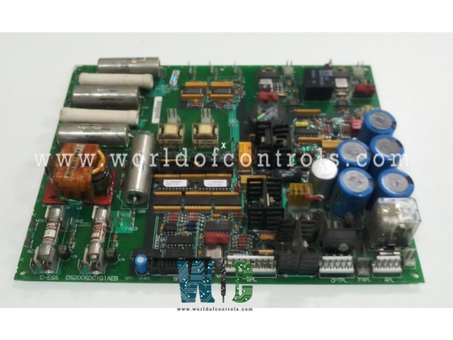
World Of Controls understands the criticality of your requirement and works towards reducing the lead time as much as possible.
DS200SDCIG1ABA - Power Supply and Instrumentation Board is available in stock which ships the same day.
DS200SDCIG1ABA - Power Supply and Instrumentation Board comes in UNUSED as well as REBUILT condition.
To avail our best deals for DS200SDCIG1ABA - Power Supply and Instrumentation Board, contact us and we will get back to you within 24 hours.
Part No.: DS200SDCIG1ABA
Manufacturer: General Electric
Country of Manufacture: United States of America (USA)
Temperature: 0 to 60 °C
Product Type: Power Supply and Instrumentation Board
Availability: In Stock
Series: Drive Control
DS200SDCIG1ABA is a Power Supply and Instrumentation Board developed by GE. It is part of Drive Control system. The Power Supply and Instrumentation Board (SDCI) stands as a pivotal component within the DC2000 drive system, offering crucial logic power and interface circuitry. This section explores the diverse circuits integrated into the SDCI board, providing an in-depth understanding of its capabilities.
The board encompasses a range of power supplies, including +5 V dc, 4 A, -15 V dc, 0.4 A, -24 V dc, and 115 V ac, 0.4 A. Additionally, it plays a role in monitoring numerous ac line and dc motor signals, such as armature current and voltage, field current, and ac line currents, voltage magnitude, and phase sequence. These monitoring circuits contribute to the comprehensive functionality of the DC2000 drive system.
An exploration of the SDCIG2 reveals its purpose in applications exceeding 10 A, where external field exciters are required. The omission of certain field power circuitry distinguishes the SDCIG2 from its SDCI counterpart.
The board receives 38 V ac from the control power transformer (CPT), rectifying and filtering it to produce unregulated +24 V dc and -24 V dc outputs. Regulators derive -15 V dc from the +24 V dc supplies. The SDCI generates a +5 V dc, 4 A output from the +24 V dc supply, with the /PSEN signal providing insights into the regulation status.
DC2000 drives equipped with the board offer non-reversing, non-plugging (NRX) motor field control. A closer look reveals its role in providing internal 10 A NRX motor field control, complete with fused field outputs, a line reactor, and snubber circuits. Visual indicators, such as neon lights, assist in promptly identifying blown fuses for efficient diagnostics.
Incorporates a field power circuit for fields up to 10 A. A detailed examination of the field power circuitry contained within the board elucidates the inclusion of snubbers and a reactor. Critical aspects, such as field power input, filtering, and protection mechanisms, are explored, enhancing comprehension of the field power circuit's functionality.
The WOC team is always available to help you with your Drive Control requirements. For more information, please contact WOC.
What is DS200SDCIG1ABA?
It is a Power Supply and Instrumentation Board developed by GE under the Drive Control series.
What role does the Power Supply and Instrumentation Board play in the DC2000 drives?
It serves as a crucial interface to DC2000 drives, enabling operational control and enhancing overall functionality.
How does the board contribute to troubleshooting capabilities?
The board incorporates LED indicators associated with each fuse, significantly improving troubleshooting capabilities. These indicators promptly signal when a fuse blows, aiding in the quick identification of potential issues.
What are the steps for inspecting the board and checking for lit indicator LED lights?
To inspect the board and check for lit indicator LED lights, follow specific steps to ensure safety and accurate assessment. Open the cabinet where the board is installed, visually inspect LED lights without direct contact, and document information about the blown fuse.
How is power disconnected from the board during the inspection process?
To disconnect power from the board, all power to the drive is removed. It's essential to test the board to ensure complete power disconnection, and a waiting period may be necessary to allow residual power to exit the board, minimizing the risk of damage.