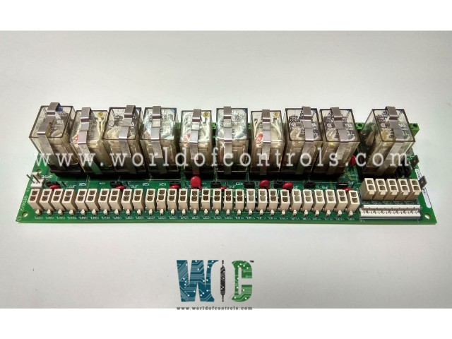
World Of Controls understands the criticality of your requirement and works towards reducing the lead time as much as possible.
DS200RTBAG3AEB - Relay Terminal Module is available in stock which ships the same day.
DS200RTBAG3AEB - Relay Terminal Module comes in UNUSED as well as REBUILT condition.
To avail our best deals for DS200RTBAG3AEB - Relay Terminal Module, contact us and we will get back to you within 24 hours.
Part No.: DS200RTBAG3AEB
Manufacturer: General Electric
Country of Manufacture: United States of America (USA)
Temperature: 0 to 60 °C
Product Type: Relay Terminal Module
Availability: In Stock
Series: EX2000
DS200RTBAG3AEB is a Relay Terminal Module developed by GE. It is a part of EX2000 excitation system. It is an optional board located within the drive (or exciter) cabinet.
The board offers ten relays that can be activated either directly from the pilot relays on the LAN I/O Terminal Board (LTB) or remotely by the user. Among these, seven relays are equipped with two Form C contacts, known as DPDT relays, while the remaining three relays feature four Form C contacts each.
The RTBA board establishes crucial communication with the LTBA board through two primary connectors: a 16-pin connector labeled RPL and a 2-pin connector named OPTPL. These connectors serve as conduits for Input/Output (I/O), facilitating the exchange of signals and data between the two boards. It's noteworthy that certain signals on the RPL connector are designated as jumper selectable, offering users the flexibility to configure these signals based on specific operational requirements.
To supply control power to designated pluggable circuits, the RTBA board features two stab connectors, namely CPH (control power hot, positive) and CPN (control power negative). The functionality of these stab connectors is not fixed but rather jumper selectable, allowing users to tailor the control power source to align with the specific needs of the pluggable circuits.
The RTBA board provides accessibility to pluggable circuits and relays K27 to K29 through distinct connectors. Pluggable circuits are accessible via connectors C1PL to C5PL and Y9PL to Y37PL. These connectors serve as entry points for external connections and additional peripherals, enriching the RTBA board's capabilities. Importantly, the control power source for these pluggable circuits is also jumper selectable, adding another layer of adaptability for users to configure as per their requirements.
For the I/O connections between the RTBA board relays K20 to K26 and external signals, the board is equipped with terminals numbered 1 to 52. These terminals serve as interface points for relays, enabling external signals to be seamlessly integrated with the RTBA board. Similar to other features, the control power source for these relays is jumper selectable, allowing users to customize the power source configuration based on the specific needs of their application.
The WOC team is always available to help you with your EX2000 requirements. For more information, please contact WOC.
What is DS200RTBAG3AEB?
It is a Relay Terminal Module developed by GE under the EX2000 series.
Is the control power source for the pluggable circuits configurable?
Yes, the control power source for the pluggable circuits is jumper selectable. This feature allows users to choose and configure the appropriate control power source for the pluggable circuits based on the specific needs of their application.
Are there any precautions to consider when configuring jumpers or replacing connectors on the board?
Yes, to prevent equipment damage and ensure safety, it is important to follow proper procedures when configuring jumpers or replacing connectors. Refer to the user manual or documentation provided with the board for specific guidelines, and always perform these tasks with the power to the system turned off.