SPECIFICATIONS
Part Number: DS200PCCAG6ACB
Manufacturer: General Electric
Series: Mark V
Product type: Power Connect Card
Availability: In Stock
Country of Manufacture: United States (USA)
Functional Description
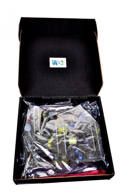
DS200PCCAG6ACB is an Power Connect Card designed and developed by GE. It is a part of Mark V control system. The Power Connect Card serves interface component within the drive system, facilitating seamless communication and coordination between the control circuitry and the SCR power bridge.
Features
- Interface Functionality: The primary function of the Power Connect Card is to establish a robust interface between the control circuitry of the drive and the SCR power bridge. It acts as a conduit for transmitting control signals, commands, and feedback between these two essential components, ensuring efficient operation and coordination within the drive system.
- Control Circuitry Integration: Within the drive system, various control circuitry components are responsible for monitoring, regulating, and controlling the operation of the drive. The Power Connect Card seamlessly integrates with these control circuitry elements, providing a standardized interface for data exchange and communication.
- SCR Power Bridge Connectivity: The SCR power bridge, comprising Silicon Controlled Rectifiers, forms a critical part of the drive system responsible for converting electrical power to the required form for driving the load. The Power Connect Card establishes a direct link with the SCR power bridge, enabling the transmission of control signals necessary for regulating power output, voltage levels, and other parameters essential for drive operation.
- Signal Transmission and Feedback: Through the Power Connect Card, control signals generated by the drive's control circuitry are transmitted to the SCR power bridge, dictating its operation and performance. Additionally, feedback signals from the SCR power bridge, such as current measurements, voltage levels, and temperature readings, are relayed back to the control circuitry, allowing for real-time monitoring and adjustment of drive parameters.
- Reliability and Efficiency: The Power Connect Card is designed to ensure reliable and efficient operation under various operating conditions and environmental factors. Its robust construction, along with advanced interface technologies, minimizes signal loss, interference, and other factors that could affect system performance, ensuring consistent and reliable operation of the drive system.
Snubber Circuits for Low-to-Medium Horsepower Controllers
- In low-to-medium horsepower controllers, the board includes snubber circuits designed to manage voltage spikes across various sections of the drive system.
- These snubber circuits play a critical role in suppressing transient voltage spikes that may occur across the AC lines, DC bus, and gate drivers during switching operations.
- By mitigating these voltage spikes, the snubber circuits help protect sensitive components, such as semiconductor devices and control circuitry, from potential damage, ensuring the reliability and longevity of the drive system.
Variations for Higher Horsepower Controllers
- For higher horsepower controllers, the design of the board may vary. In some cases, certain or all of the snubber circuits may be omitted from the PCCA board.
- Instead, these snubber circuits may be relocated and integrated elsewhere within the system architecture to accommodate the specific requirements and operational characteristics of higher horsepower applications.
- By relocating the snubber circuits, system designers can optimize the layout and distribution of components within the drive system, ensuring efficient operation and minimizing potential interference or limitations imposed by space constraints on the board.
Optimization for System Requirements
- The inclusion or omission of snubber circuits on the board is determined based on the specific requirements and characteristics of the drive system, particularly its horsepower rating and operational environment.
- This modular approach allows for flexibility in system design, ensuring that the board is tailored to meet the unique needs of different applications while maintaining optimal performance and reliability.
Configurable Jumpers
- JP1 and JP2 Jumpers: Jumpers JP1 and JP2 are wire jumpers that need to be appropriately connected to stab terminals P3 through P10 on the board. The specific terminals to which JP1 and JP2 should be connected are determined by the card group number and system voltage. These connections are critical for ensuring proper voltage regulation and control within the system.
- WP3 and WP4 Jumpers: Jumpers WP3 and WP4 serve a different purpose, connecting stab terminals P2A to P2B and P1A to P1B, respectively. These jumpers are utilized to select whether the snubber capacitors are connected to the same point on the power bridge as the voltage feedback channel. The configuration of WP3 and WP4 jumpers impacts the overall performance and behavior of the snubber capacitors, ensuring effective suppression of voltage spikes and transient disturbances in the system.
- Configuration and Placement: The placement of wire jumpers, as well as their connections to specific stab terminals, is determined based on various factors, including the PCCA board group number and system voltage.
WOC is happy to assist you with any of your GE requirements. Please contact us by phone or email for pricing and availability on any parts and repairs.
FREQUENTLY ASKED QUESTIONS
What is DS200PCCAG6ACB?
It is an Power Connect Card designed and developed by GE
What are the configurable jumpers on the board, and what are their functions?
The configurable jumpers on the board include JP1, JP2, WP3, and WP4. JP1 and JP2 determine connections to stab terminals for voltage regulation, while WP3 and WP4 select connections for snubber capacitors and voltage feedback channels.
How do I determine the correct connections for JP1 and JP2 jumpers?
The connections for JP1 and JP2 jumpers depend on the card group number and system voltage.
