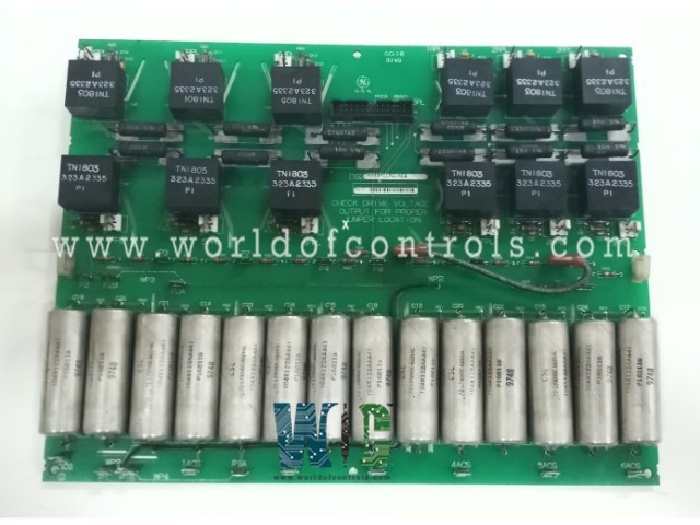
SPECIFICATIONS
Part No.: DS200PCCAG1ACB
Manufacturer: General Electric
Country of Manufacture: United States of America (USA)
Temperature: 0 to 60 oC
Manual: GEI-100161
Product Type: Power Connect Card
Availability: In Stock
Series: EX2000
Functional Description
DS200PCCAG1ACB is a Power Connect Card developed by GE. It is a part of EX2000 system. The Card stands as a crucial component in the intricate design of a drive system, serving as the intermediary between the control circuitry of the drive and the SCR power bridge. This interface is pivotal for the seamless integration and efficient functioning of the drive, ensuring a controlled and optimized power flow.
Features
- One of the distinctive features of the board is its utilization of pulse transformers to deliver the necessary gate drive to the SCR power bridge. This gate drive is instrumental in regulating the firing sequence and control of the SCRs, thereby managing the power flow through the system. The pulse transformers act as a key link in this process, facilitating precise and controlled communication between the control circuitry and the power bridge.
- For low-to-medium horsepower controllers, the board goes a step further by incorporating snubber circuits. These circuits play a crucial role in managing and controlling voltage spikes across various critical points within the system. Specifically, they address spikes across the AC lines, the DC bus, and the gate drivers. By incorporating these snubber circuits directly onto the PCCA, the system gains enhanced protection and stability, particularly in scenarios where lower to medium levels of power are being managed.
- However, in the case of higher horsepower controllers, the design may vary. In such instances, some or all of the snubber circuits are omitted. Instead, these circuits find their placement elsewhere within the broader system architecture. This strategic decision is made to optimize the overall design, efficiency, and performance of the higher-powered controllers, allowing for a more distributed and specialized approach to snubber circuitry.
Hardware Configuration
- Configurable Jumpers: The board is equipped with configurable jumpers that enable users to customize specific settings and connections based on the requirements of the drive system. Jumpers are small connectors that can be fitted onto designated pins on the board, allowing for the establishment or interruption of electrical pathways. This configurability is advantageous as it provides adaptability to different system configurations and operational needs.
- Wiring Plug Connectors: Wiring plug connectors are another integral part of the hardware. These connectors facilitate the establishment of secure and reliable electrical connections between the board and other components within the drive system. By using these connectors, the installation and maintenance processes are streamlined, allowing for efficient assembly and disassembly when needed. The use of plug connectors enhances the modularity of the system, simplifying both initial setup and future modifications.
- No LEDs, Fuses, Test Points, or Switches: Unlike some other electronic boards, the PCCA intentionally omits certain components such as LEDs, fuses, test points, and switches. LEDs are typically indicators, fuses protect against overcurrent, test points facilitate diagnostics, and switches control specific functionalities. The absence of these components on the PCCA board suggests a reliance on the configurability of jumpers and the simplicity of plug connectors for customization and connectivity purposes.
Configurable Jumpers
- JP1 and JP2 Jumpers: These two jumpers, JP1 and JP2, are vital components that need to be connected to the appropriate stab terminals P3 through P10. The specific connections depend on factors such as the card group number and system voltage. Configuring JP1 and JP2 correctly is essential for establishing the right electrical pathways and ensuring compatibility with the unique specifications of the power system. These jumpers essentially act as switches, directing the flow of current according to the determined parameters.
- WP3 and WP4 Jumpers: WP3 and WP4 serve a distinct purpose by connecting stab terminals P2A to P2B and P1A to P1B, respectively. These jumpers play a key role in the selection process, determining whether the PCCA snubber capacitors are connected to the same point on the power bridge as the voltage feedback channel. This configuration is crucial for managing and controlling voltage spikes effectively. The jumpers, in this context, offer a means of tailoring the snubber capacitor connections to the specific requirements of the power system, enhancing overall system stability and performance.
The WOC team is always available to help you with your EX2000 requirements. For more information, please contact WOC.
Frequently Asked Questions
What is DS200PCCAG1ACB?
It is a Power Connect Card developed by GE under the EX2000 series.
What are the designated jumpers on the PCCA board?
The board features four wire jumpers designated as JP1, JP2, WP3, and WP4.
What is the role of JP1 and JP2 jumpers?
JP1 and JP2 jumpers play a critical role in selecting system voltage and determining specific electrical connections. Proper configuration is essential for alignment with the card group number and system voltage.
How do JP1 and JP2 jumpers contribute to system customization?
By connecting JP1 and JP2 to the appropriate stab terminals P3 through P10, these jumpers allow users to customize the electrical pathways based on the card group number and system voltage, ensuring compatibility with specific power system requirements.
What is the purpose of WP3 and WP4 jumpers on the PCCA?
WP3 and WP4 jumpers are crucial for determining snubber capacitor connections. They facilitate the selection of whether the snubber capacitors are connected to the same point on the power bridge as the voltage feedback channel.
